Collector Base Junction

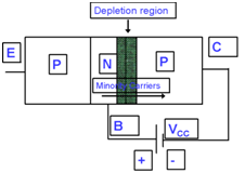
This fig exhibits the Collector-base junction where collector is built up of P-type material and Base is made through N-type material. In fig +ve terminal of the battery is attached to Base whereas -ve terminal is attached to the Collector. It means this junction will go in reverse-biased mode and depletion layer will be broadened and the current will flow because of minority carriers.

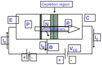
In fig given above +ve terminal of the battery is attached to Emitter whereas -ve terminal of VEE is attached to the the Base whereas on the right side of this fig +ve terminal of the battery VCC is attached to Base and -ve terminal is associated to the Collector. There are 2 depletion layers in fig in which one is small whereas the other is bit wider and this is because of the forward biased of emitter-base junction and reverse biased because of the collector-base junction. We also observe the emitter current IE will flow inward that is pointing into the transistor, though the base current IB and collector current IC is exhibited going outward from transistor.