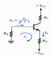
Biasing taking two power supplies

The loop equation for the loop marked as L is

Example: The bias arrangement given in the figure is to be utilized in common base amplifier. Make the circuit to generate a dc emitter current of 1mA and give the highest possible gain while permiting for a maximum signal swing of ±2V at the collector. Take +10V and -5V power supplies.

Solution:
As the amplifier is to utilized in common base configuration, thus the circuit will take the shape as given.

Thus
RB=0
Taking the base-emitter junction forward biased , the emitter resistance can be calculated as
RE=(-0.7-(-5))/1m=4.3kW
So as to permit for ±2V signal swing at the collector, whereas selecting as larger value of RC as possible, set VC=+2V, thus -2V signal would not saturate the BJT. Therefore
RC= (10-2)/IC
= 8/1mA
RC = 8kW