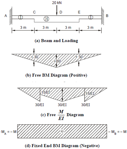
Find the fixed end moments and the vertical support reactions:
Example
Find the fixed end moments and the vertical support reactions for the fixed beam shown in Figure 16. Draw the BM and SF diagrams.

The moment of inertia in the central portion CE is double that of the end portions AC and EB.
The free beam BM diagram is shown in Figure 16(b). This is a triangle with apex below the load point D (which is also the midpoint of the beam).
The maximum ordinate of the triangle at D is (20 × 12)/4 = 60 kNm .
By similar triangles the value of BM at C and E are 30 kNm. For obtaining the M/EI diagram we divide by EI in the region AC and EB, and by 2 EI in the region CE. Thus, we obtain the M/EI diagram as shown in Figure 16(c).
Similarly, by symmetry the fixed end (negative) bending moments MA and MB must be equal say - M, and the diagram is a rectangle as shown in Figure 16(d). For the regions AC and EB the ordinates of the M/EI diagram is - M /EI and for the region CE it will be - M/2 EI as shown in Figure 16(e).
Thus, there will be three rectangles as shown in Figure 16(e).
Since the slope at fixed ends at A and B are both zero the change in slope from A to B is zero. So by the first moment area theorem the net area of the final (superimposed) M/EI diagram should be zero. Meaning thereby, that positive M/EI diagram and negative M/EI diagrams have equal areas.
Now the positive M/EI diagram consists of two triangles and two trapeziums hence the total areas as can be easily seen are
Positive M/EI area = 2[ 30/EI x 3/2 + (15+30)/El x3/2
Negative M/EI area =2 [M/EI x3 + M/2EI x3]
∴ 2[30/EI x3/2 +45/El x3/2 ] +2 [M/EI x 3+ M/2EI x 3 ] =0
giving M = - 25 kN m, which is the value of the fixed end moment MA and MB. These moments are hogging (- ve) moments.
The final BM diagrams are shown in Figure 16(f). By Eq. (2.22(a))
VA = Pb/I + Pab /I3 (b - a) = (20 × 6)/2 + (20 × 6 × 6)/123 (6 - 6) = 10 kN
Similarly, VB = 10 kN .
It can be easily seen that the points of centraflexure (zero BM) are 2.5 m from the end supports.
The final SF diagram is shown in Figure(g).
[Note : It may be noted that in the case of the fixed beam AB having constant EI the fixed end moments M A = M B = - (20 × 12 )/8= - 30 kNm . The extra stiffness provided in the central zone decreases the value of the end fixing moment.]