Reach-ability Graph
A reach-ability graph for an initially marked Petri net M0, is a directed graph (V, E), here V = R [M0] is a set of vertices, and E, the set of directed arcs, is specified by as:
(M1 , M2 ) ∈ E , if
- M1 , M 2 ∈ R [M0 ] and
- Either there exists a transition t ∈ T
 such that or there exists a set, T1 ⊆ T , such as T1 is a set of concurrent transitions by firing all of that M1 reaches M2
In the reach-ability graph, the nodes are labeled by markings they show and the directed arcs are labeled by transitions or the set of concurrent transitions that firing takes the source node to the destination node.
Illustration .7
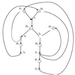
From the Petri net shown below in Figure (a)
- In a tabular form, show the reachable markings of the Petri net.
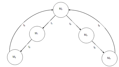
- Draw the reach-ability graph.

Solution
Reach-able marking of Petri net of above figure (a) are represent in Table no.2 below.
Table no.2: Reachable Marking of Petri Net Shown in above figure (a)
|
|
p1
|
p2
|
p3
|
p4
|
p5
|
p6
|
p7
|
|
M0
|
1
|
1
|
1
|
0
|
0
|
0
|
0
|
|
M1
|
0
|
0
|
1
|
1
|
0
|
0
|
0
|
|
M2
|
1
|
0
|
1
|
0
|
1
|
0
|
0
|
|
M3
|
0
|
0
|
0
|
0
|
0
|
1
|
0
|
|
M4
|
0
|
1
|
1
|
0
|
0
|
0
|
1
|
In above table, M0, M1, M2, M3, M4 represent the different reachable markings. These markings can be shown in the form of a reach-ability graph.

Figure: A Reach-ability Graph of a Marked Petri Net Model of a System as Shown in above figure (a)