Magnetic Circuits:
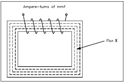
A magnetic circuit could be compared along with an electric current in that EMF, or voltage, generates a current flow. An ampere-turns (NI), or the magnetomotive force (Fm or mmf), will produce a magnetic flux Φ show in the Figure. The mmf could be compared along with EMF and the flux ( ) could be compared to current. Equation (1-16) is the mathematical representation of magnetomotive force derived by using Ohm's Law, I= E/ R.
Φ = FM/R = mmf/R (1-16)
where
Φ = magnetic flux, Wb
Fm = magnetomotive force (mmf), At
R = reluctance, At/Wb

Figure: Magnetic Current with Closed Iron Path
Equation (1-17) is the mathematical representation for reluctance.
R = L/µA (1-17)
Where
R = reluctance, At/Wb
L = length of coil, m
µ = permeability of magnetic material (T-m)/At
A = cross sectional area of coil, m2
Example: A coil has a reluctance of 3 x 10⁶ At/Wb and an mmf of 600 At, Find out the total flux .
Solution:
Φ = mmf/R
Φ = 600At/ 3 x 10⁶ At/Wb = 200 x 10-6 Wb = 200µWb