Expression for the time period:
An expression for the time period of the output waveform can be determined as follows. The equation for the capacitor charging may be written in the following general form.
Vc (t ) = A + B e - t /( RA + RB ) C
where A and B are constants which may be resolute from the following conditions.
at t = 0, Vc (t ) = Vcc / 3
at t = ∞ , Vc (t) = Vcc
Substituting in Eq. (97), we determine
Vcc = A + B and Vcc = A
from which it is found that
∴ B = 2Vcc /3
Eq. (97) now becomes
Vc (t) = Vcc - (2/3) Vcc e- t /( RA + RB ) C
Now at t = TH, VC (t) =(2/3)Vcc ,therefore, we get
(2 /3)V cc = V cc - (2/3) V cc e (- tH/( RA + RB ) C)
(2/3) e - tH/ ( RA + RB ) C = 1/3
e tH/ ( RA + RB ) C = 2
from which the needed time period is given by
TH = (RA + RB ) C ln 2
likewise, one can determine that considering the equation for discharge of the capacitor with time constant CRB, one may find TL as
TL = RB C ln 2
The frequency of the output waveform is, thus, given by
f = 1 / (RA + RB ) C ln 2
and the duty cycle is given by
f = (RA + RB ) (RA + 2RB )
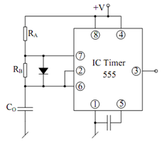
Note down that even if one selects RA = RB, the duty cycle may not be made 50%. However, the duty cycle may be made 50% by RB shunting by a diode as illustrated in Figure

Figure: Astable Multivibrator with 50% Duty Cycle
This makes TH = RA C ln 2 and TL= RB C ln 2, so that the duty cycle is given by
δ= RA /RA + RB
which would become 50% for RA = RB.