Development of a Sine-Wave Output:
At the instant the loop is within the vertical position that was show in the Figure, the coil sides are moving parallel to the field and do not cut magnetic lines of force. Within this example, there is no voltage induced in the loop. Since the coil rotates within a counter-clockwise direction, a coil sides will cut the magnetic lines of force within opposite directions. A direction of the induced voltages depends on the direction of movement of the coil.
The induced voltages add in series and making slip ring X (Figure) positive (+) and slip ring Y (Figure) negative (-). A potential across resistor R will cause a current to flow from Y to X by the resistor. This current will rise until it reaches a maximum value whenever the coil is horizontal to the magnetic lines of force that were show in the figure. A horizontal coil is moving perpendicular to the field and is cutting the greatest number of magnetic lines of force. Since a coil continues to turn, the voltage and current induced reduce until they reach zero, whereas the coil is again in the vertical position. Within the other half revolution, an equivalent voltage is generating except in which the polarity is reversed. The current flow by R is now from X to Y (Figure).
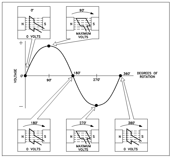
Figure: Developing a Sine-Wave Voltage
The periodic reversal of polarity results in the generation of a voltage, as display in Figure. The rotation of the coil by 360° results in an AC sine wave output.