Static Balancing Machines:
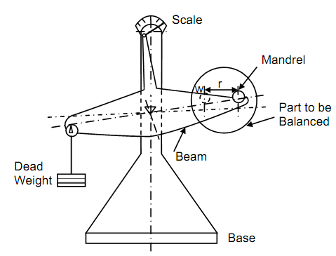
A very simple balancing machine to find out-of-balance disc and ring is illustrated in Figure 15. Essentially it consists of a heavy base extended in a column to adequate height. This carries a scale on which a needle indicator moves. The scale might read unbalance in units of Nm. A beam or an arm is supported on a knife edge close the middle of the height. While left to itself the beam shall be horizontal. At one ending of the machine a mandrel may be carried in a matching groove. On the other end same mandrel shall carry a hanger to support dead weight.
Rotating part, whose balance is to be checked, is located on mandrel that is placed in groove as illustrated. Dead weights are located in hanger to bring the indicator near zero on the scale to specify that the dead weight may balance the weight of part. The partition is then rotated or displaced on mandrel either by hand or by a motor to see if the beam remains horizontals in all location of the part to be balanced. If there is extra mass in the part as indicated by small circle at a distance from r from the centre then the beam shall tilt towards the dead weight as illustrated in Figure 15. If the extra mass moves to far off position then the beam shall tilt in the direction of the part. The extra mass being anywhere among extreme horizontal to extreme vertical location will cause the beam to occupy some intermediate location.
Static Balancing Machine
If unbalance is detected then attempt is made to determine its highest value that can be read on scale. Imagine the observed value is C that can be regarded as W r.
The balance can be attained by removing a mass W at the radius r on left of mandrel or adding up a mass W at a radius r on right of mandrel. This kind of machine is utilized for wheels and discs of small width as automobile tyres that can be balanced by adding up small weights on rubber tyre. The static balance shall result in stationary indicator while the disc or tyre is rotated in the mandrel.
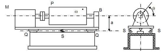
Still another arrangement for finding static unbalance is illustrated in Figure 16. This machine contains much higher sensitivity like the condition of resonance is utilized. The machine consists of a cast iron depend on the top of which a cradle is supported on knife edge supports Q, Q on the central line. On either side of the knife edge support springs S, S is placed among the base and the cradle. An electric motor M, located on the cradle is linked to the part P through a flexible coupling. The partition to be balanced that is in shape of cylinder is supported in bearing B at the other end. The whole system shall have a precise natural frequency. The part P to be balanced might have a small unbalance because of tiny mass of weight w at a radius r. the centrifugal force of w that means W/g ω2 r acts in radial direction, making an angle θ along the horizontal. Its horizontal component is W ω2 r cos θ and it will be Wω2 r while w is on horizontal radius. The force shall tend to cause the cradle to rock about Q, Q which will be damped by the springs S, S. If the speed of motor is slowly increased it might coincide with the natural frequency of cradle and after that resonance shall occurs causing cradle to shake violently. Therefore, even smallest static unbalance shall be detected. The dynamic unbalance shall not be detected as the moment shall be in the plane of the knife edges that will not permit the cradle to oscillate.