Measurement of Unbalanced Force and Moment:
In dynamic balancing machine as separate device is utilized for measurement of force and couple that are not balanced. The fundamental principle is to apply known force & couple on the cradle in a direction to oppose the influence of disturbance. It is achieved by rotating masses that are statically balanced on vertical shaft however being in different planes (parallel planes) exert a moment in vertical plane that is transferred to cradle. It imposed moment may be calculated and varied by modifying the distance among planes of rotating masses and also be modifying their relative location in the parallel planes. Therefore, the device needs rotation of shaft, change of distance among the planes of rotation of masses & the angular location of the masses in parallel planes. Yet another need will be to influence the changes while the part to be balanced (P in Figures 17 and 18) is rotating on the cradle.
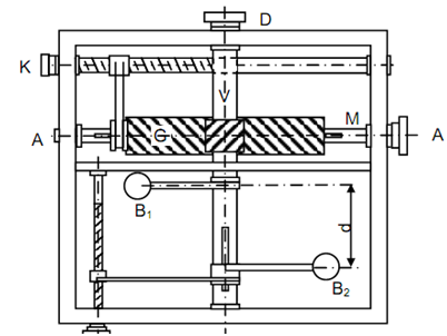
The construction & working of the device is explained with the help of Figure 19. The cradle is free to slide and long sufficient to accommodate the calculating device whose shaft AA is placed in line along the axis of the partition to be balanced.
Placed on cradle to shaft AA shall be rotated by the motor. AA carries a spiral gear, G, that meshes with same spiral gear on vertical shaft DD. The gear G is much broader and may slide on AA. While it slides on AA, it causes spiral gear on vertical shaft DD to rotate. The vertical shaft carries to eccentrically placed masses B1 and B2 that are equivalent in weight & rotate at the similar radius. They are located in static balanced. The mass B1 is fixed in location however the arm of B2 may slide on shaft DD so the distance among the planes of B1 and B2 (illustrated d can change). For sliding arm of B2 the screw H is rotated that rotates in a nut that carries an arm supporting the arm of B2. Its downward slide is under its own weight.
Keep in mind that the vertical shaft DD rotates at the similar speed as the part to be balanced that is coupled directly to the shaft AA. The equal masses B1 and B2 (equal to B) shall create centrifugal couple equivalent to
(B/g) ω2 b . d
This couple might be resolved into two components. These are following :
(B /g)ω2 b . d cos φ . . .
(i)
in a vertical plane at right angles to the axis of shaft AA and
(B/g) ω2 b . d sin φ . . .
(ii)
in a vertical plane parallel to the axis of rotation of AA.
If the axis of knife edge AA is parallel to edge AA, as in static balance machine of Figure .2 the effective component to neutralise the cradle oscillations is (a). If the knife edge axis QQ is perpendicular to the axis AA the influenced balancing couple is (b). This moment must neutralise disturbing couple w/g ω2 r l sin θ .
(iii)
(B/g) ω2 b . d sin φ = (W /g )ω2 r l sin θ . . .
is the condition that the cradle shall not rock regarding the knife edge axis. This needs that
sin φ= sin θ or φ =θ --------------- (iv)
This condition is attained by rotating K and φ may be read.
From Equation (iii)
B b d =ω r l ------------------(v)
While the cradle is not vibrating.
All of the quantities on left hand side of Equation (v) are read from measuring device. l is found by adjusting the location of part to be balanced as depicted in Figure 4. Therefore, wr is find out.