Dynamic Balancing Machine:
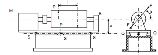
The cradle in machine of Figure 16 might be made to rock regarding knife edge if it is located in the centre as illustrated in Figure 17. The axis of knife edge, QQ is perpendicular to axis is rotation, MB. Presence of unbalanced force or an unbalanced moment shall cause the cradle to rock regarding the knife edge axis, QQ. This machine (Figure 3), therefore is a dynamic balancing machine. Earlier than any part is tested in this machine it must be statically balanced so that just effect of unbalanced moment is observed. If the long part (say a cylinder) is statically balanced it might still be in dynamic unbalanced because of the moment W/g ω2 r l sin θ . Note down that other component of moment W /g ω2 r l cos θ acts in horizontal plane and therefore does not cause cradle to vibrate.

Dynamic Balancing Machine
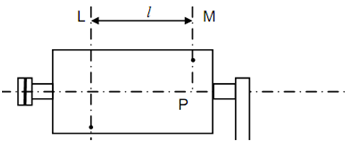
A machine alike to one in Figure 17 is achieved after small modification to balance the part without first balancing statically it. The principle is depending on the fact that masses rotating in various parallel planes might be balanced by providing balance masses in two arbitrarily selected parallel planes. This was shown in Unit 18. The part P to be balanced is to mounted that plane L, one of the two parallel planes in which balance weight is to be placed, coincides along the knife edge as illustrated in Figure.

In this case the unbalanced moment shall be caused by the unbalance influence in plane M that can be measured and correction applied. In the machine the part is readjusted either by deleting and refixing or by modifying position of the cradle along slides (guides) given for the cause. With the readjustment now the plane M is made to coincide along the knife edge axis. Thus the out-of-balance influence will cause a moment regarding knife edge axis that can be measured and correction applied.