Determine the weight of the reciprocating parts for the second cylinder:
A four cylinder vertical engine contain 300 mm long crank. The planes of rotation of the first, third and fourth cranks are 750, 1050 and 1650 mm from that of the second crank and their reciprocating masses weigh respectively 1500 N, 4000 N and 2500 N. Determine the weight of the reciprocating parts for the second cylinder and the relative angular positions of the cranks so that the engine is in complete primary balance. Each of connecting rod is equal to 1350 mm long and the speed is equal to 150 rpm.
Solution
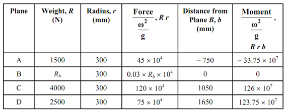
The problem of multi-cylinder in-line engine is similar as that solved out in Unit 19 for various masses revolving in parallel planes. The reciprocating masses may be transferred to crank pin (supposed as transferred) for analysis. Therefore, we have situation of cranks rotating in parallel planes placed at specific distances (such like bA = distance of plane A from plane B) from reference planes. Here we will suppose four planes A, B, C and D in which cranks are rotating and all of cranks have similar length as 300 mm. Thus we insert the data in following table and compute forces as proportional to R r and moments regarding reference planes (B in this case) as proportional to R r b.

From moment polygon the angular placement of cranks can be computed. The polygon of moments is drawn by representing a moment through the side of the polygon in the direction of the crank. If moment vector points from axis of the shaft to the crankpin, the moment is +ve and if this points from crankpin to the axis the moment is -ve. As may be seen from above Table 1 the moment of centrifugal force because of mass in plane A taken regarding plane B is negative. Therefore, the moment 33.75 × 10⁷ shall be represented by a line that will point to the axis from crankpin. The other two sides shall represent positive moments. To draw the moment polygon in Figure 14, we must depend upon the fact that three sides shall close the polygon.
We begin withdrawing crank OA of plane A and side oa of polygon parallel to AO. Thus the side oa of the polygon of moments in Figure 14 of previous chapter 20 is achieved being equal to 33.75 × 10⁷. With a and o as centers draw arcs at radii of drawn equivalent to 126 × 107 and 123.75 × 10⁷, respectively along the help of the compass. The two arcs intersect with c to complete polygon. Thus the cranks OC & OD are found in direction by drawing lines OC & OD parallel to ac & cd, respectively and therefore angular position of cranks in planes C & D is resolute. The angles α and β may be resolute by measurement. Note down that the angular location of crank in plane B is yet to be resolute.

Cranks Moments Polygon Force Polygon
For finding the angular location of crank in plane B we draw the force polygon in Figure 14 that must close for primary forces are balanced. The closing side shall be representing the centrifugal force of mass at B, others being known from column 4 of the above Table 1. Keep in mind in this case forces shall point away from axis toward crankpin.
By measurement α = 85o, β = 79o, γ = 30o -------------- (i)
(Note: While we draw polygon of moments we supposed C to be on right hand side of A in crank arrangement. We might have taken D on the right hand side and C on left of A. In the second case B must turn out to be on right of vertical line in crank arrangement.)
The length ob measures 85.5 × 10⁴.
∴0.03 Rb × 104 = 85.5 × 10⁴
∴ Rb = 2850 N (ii)
The relative locations of the cranks are indicated in Figure.