Complete Balance of a Single Cylinder Engine:
We may draw conclusion that complete balance, comprising balance of primary & secondary forces and secondary and primary moments, is not possible normally. However, in a single cylinder engine, we may create design that might satisfy the condition of complete balance. Our description below shall show that such a proposal though might be feasible, shall increase the expense and make a single cylinder engine much bulkier than along partial balance.
The crank is supposed to make angle θ along the line of stroke. The reciprocating mass of weight R, may be supposed to be placed at crankpin (crank radius) in which case it shall cause a centrifugal force equivalent to R/g ω2 r cos θ along the line of stroke that acts on the foundation. This is the primary disturbing force. The secondary disturbing force shall be
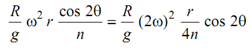
that can be regarded to be generated by a weight R, located on a crankpin of crank of length r/4n at a speed of two times the speed of actual crank.
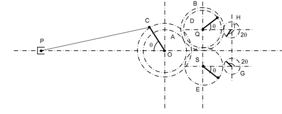
The arrangement that shall produce complete balance is illustrated in Figure 8. We shall primary explain the figure totally and then see if total balance is achieved.
On the crankshaft is mounted a gear A which shall rotate along the speed of crank shaft and in the similar direction.
A is in mesh along gear B of similar number of teeth and mounted on shaft Q. A gear D of smaller number of teeth is mounted on Q. The gear D rotates at similar speeds on crank however in opposite direction to the crank. Gear D is so mounted that its pitch circle touches the line of stroke and another gear E of similar number of teeth (identical) is mounted on other side of line of stroke and thus E will move in the similar direction as the crank OC. A weight W/2 is located on the wheel E at a distance of r on the line which makes angle θ with the line of stroke as illustrated. Another weight W/2 is placed at the radius r on gear D at an angle θ with the line of stroke as illustrated in Figure 8. The radial line from S on E is known as direct crank and the radial line from Q on D is named reverse crank. The direct crank moves along the speed and in the direction of engine crank when the reverse crank moves along speed of the engine crank in the opposite direction.
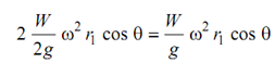
The centrifugal force because of each of masses located on direct and reverse cranks is (W/2) ω2 r1 and its component on the line of stroke is W/2 ω2 r1 cos θ towards right of O along the line of stroke. The total of 2 components of both the forces, that means centrifugal forces of masses on direct and reverse crank is
 ------------------ (i)
The total of components of centrifugal forces because of W /2 on direct and reverse cranks in the direction perpendicular to stroke is
(W/2) ω2 r1 sin θ - (W /2) ω2 r1 sin θ = 0 (ii)
That means that the direct and reverse crank masses do not generated force component perpendicular to the line of stroke.
Because of weight of reciprocating masses, R, of the engine the disturbing force (primary) toward left on O along the line of stroke is
F p = R/ g ω2 r cos θ . . . (iii)
For total balance of primary disturbing force the quantities on right hand side in (i) and
(ii) must be equal
That means
(W/g )ω2 r1 cos θ= (R/g) ω2 r cos θ
Or W r1 = R r -------------------(iv)
Or (W/ 2) r = R (r/2) -------------------- (v)
If this condition is satisfied the primary disturbing force is completely balanced along the line of the stroke however perpendicular to the line of stroke the force (R/g) ω2 r sin θ remains and this is maximum of the magnitude (R/g) ω2 r.
In case of partial balance as was discussed in previous unit the force is higher than this, on the frame. However the design of the system needing three gears is added and alignment must be perfect so that the resultant force in (i) must be aligned with the line of the stroke, to ignore any unbalanced moment on the crank shaft.
The Figure 8 illustrated other two gears H & G meshing with D and E respectively and having number of teeth half of the mating gears. Therefore the angular velocities of H and G are twice that of engine crank and they carry rotating masses on radial lines from shafts T & U, respectively at the similar radius.
The secondary force (disturbing) because of piston acceleration on the engine frame with the line of stroke to the left is
F = (R/g) (2ω)2 (r /4n) cos 2θ -------------- (vi)
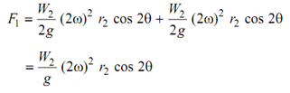
The components of forces because of centrifugal force of weights at radius of r2 in each of H
& G, with the line of stroke result in
 (vii)
(vii)
For balance of secondary force in (vi)
Or W2 r2 = R (r/4n)
W2 /2 is the weight of mass associated to gears H & G at radius of r2 in each of H and G.
Practically specking the method is extremely cumbersome but the arrangement has been utilized for secondary force balance in some engines.