Balancing of Three-Cylinder Radial Engine:
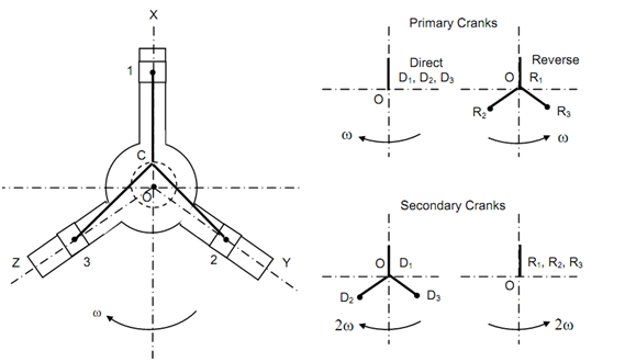
A three-cylinder might have in-line or radial configuration. A radial configuration in which cylinders are placed at 120o angles in illustrated in Figure 9. All of the connecting rods (three in number) are coupled directly to a single crank. Therefore, there are two bearings in which the crankshaft is supported. For convenience we represent three centre lines like OX, OY and OZ. We suppose that reciprocating parts of all three cylinders are alike. The lengths of cranks and connecting rods are similar. In the position illustrate in Figure 8 the crank of cylinder 1 makes an angle zero along the line of stroke while in the similar position cranks of 2 & 3 makes angle of 120o and 240o with respective lines of stroke. Therefore, the primary direct cranks coincide however reverse crank of 2 shall be at 120o from OY and reverse crank of 1 remains in the similar position. (For determining the position of reverse crank you might take the mirror image by imagining a mirror placed along the line of stroke.)
The secondary direct cranks make angle 2θ along the line of stroke. Therefore, the secondary direct crank of cylinder 1 is with OX. The secondary direct crank of cylinder 2 makes angle of 2 × 240 along the line of stroke OY. The secondary direct crank of cylinder 3 makes an angle of 2 × 120 along the line of stroke OZ. The secondary reverse cranks are the mirror images of the direct cranks, therefore they coincide along OX.
Both of primary and secondary cranks are illustrated on the side of engine in Figure 9.
In Figure 9 note down that cranks have been drawn as they present and imagined (the reverse cranks are imagined). Each of cranks carries half of reciprocating mass at the crank pin. The radius of the primary crank is r (radius of definite crank) & radius of secondary cranks is r where n is the ratio of crank length to crank radius. When primary cranks rotate at ω rad/s which is the speed of engine the secondary cranks rotate at 2ω. Since angles are measured from line of stroke in clockwise direction that means the direction of rotation of the engine crank.

For investigative the balancing of the engine (without any extra from outside) we may see that primary reverse cranks current balanced system while primary direct cranks provide addition of three forces upward that means along OX.
The unbalanced force is
Fp = 3 ×( R/2g) ω2 r
(a)
Looking at the secondary cranks we see that the direct cranks present balanced system however the reverse cranks causes unbalanced force again in the direction of OX.
The unbalanced secondary force is
Fs = 3 × (R /2g) (2ω)2 (r /4n)
(b)
Fs revolves opposite to crank along speed of 2ω. When the crank is with the line of stroke along piston at top, the direct primary (Fp) and reverse secondary forces shall add up.
For instance in a three-cylinder radial engine of the kind illustrated in Figure 9, the three connecting rods are coupled to a single crank directly which contain a radius of 62.5 mm and length of each connecting rod is equal to 225 mm. The weight of reciprocating mass of each cylinder is equal to 20 N. The crank is rotating at 1500 rpm. We need to calculate resultant unbalanced primary and secondary forces.
ω= (2 ×π × 1500)/60 = 157.08 rad/s
n = l /r = 225 /62.5 = 3.6
R = 20 N
∴ Fp = 3 × (20/ (2 × 9.81)) × (157.08)2 × 62.5 × 10- 3 = 4716 N
and

By balancing of primary force can be attained by placing a balance mass opposite to the crank at a radius, r1. We can select r1 conveniently that is one that can be accommodated in engine. Let us select r1 = 87.5 mm, the balance weight of W1.
Then
W1 r1 = (3/2) R r
∴ W = (3/2)( R r / r1)= (3/2) ((20 × 62.5 )/87.5) = 21.45 N