Balancing Of In-Line Engines With Identical Reciprocating Parts For Each Cylinder:
The high speed multi-cylinder engines (in-line cylinders) are broadly utilized and they are internal combustion engines, therefore the fuel is fired in different cylinders at different times. This is not complicated to understand that firing shall occur when piston shall be at top dead centre along crank making zero angles along line of stroke. However, it should be understood that in four stroke engine the piston shall be at top dead centre two times throughout a cycle in which cylinder shall fire once. Alternatively in two stroke engine the piston shall be at top dead centre just once throughout a cycle in which cylinder shall fire once.
If Nc = Number of cylinders, and
α = Angular spacing of the cranks round the shaft.
After that in four stroke engines the consistent firing strokes will be attained if
α= 4π/ Nc
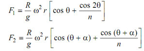
The inertia forces of primary & secondary nature for reciprocating parts of each of the cylinder might be calculated by application of reverse and direct primary and secondary cranks. The inertia force (primary and secondary both) still can be expressed as
 .... (i)

By providing uniform firing order ensures that F1, F2, etc. shall be balanced if the cylinders fire in the order 1, 2, 4, 6, etc. Clearly Nc = 3 or 5 shall leave some unbalanced force & external balancing might be needed.
The balancing of moments can be attained if the crank shaft is symmetrical regarding some plane. The cranks might be arranged in pairs if number is 4, 6, 8, etc. The pairs shall be made by parallel cranks that are situated at equivalent distances through plane of symmetry. This condition shall be satisfied just if engines consist of even number of cylinders.
For instance, let a four cylinder engine of four stroke kinds. Uniform firing interval shall result if cranks are spaced at α= 4π/ Nc = π . It will make two pairs of cranks set at 180o, as illustrated in Figure 10.

If we compute inertia forces because of identical reciprocating masses by separating forces
F1, F2, etc. (Equation (i)) into primary & secondary forces we see that
Fp1 = (R/g) ω2 r cos θ
Fp 2 = (R/g) ω2 r cos (θ + π) = -(R/g)ω2 r cos θ
Fp 4 = (R/g) ω 2r cos (θ + 2π) =(R/g)ω2 r cos θ
Fp3 = (R/g) ω2 r cos (θ + 3π) = - (R/g)ω 2r cos θ
∴ ∑ F p = (R / g) ω2 r (cos θ - cos θ + cos θ - cos θ) = 0
that shows that primary forces are balanced.
Again from equation (i) it is not hard to see that secondary forces are not balanced.
Assume
R (2ω)2 . r /4n = Ks
Fs1 = K s cos 2θ
Fs 2 = K s cos 2 (θ + π) = K s cos 2θ
Fs 4 = K s cos 2 (θ + 2π) = K s cos 2θ
Fs 3 = K s cos 2 (θ + 3π) = K s cos 2θ
∴ ∑ Fs = 4K s cos 2θ
This can be seen that the moments of primary forces regarding the central plane shall vanish if the distance among cylinders 1 and 2 must be same as that among 3 and 4. The firing order in such an engine shall be 1, 2, 4, 3. If we begins cycle along piston 1 at top of the cylinder while firing take place in 1, after that after half a revolution the cylinder 2 fires, after another half revolution cylinder 4 fires, followed by firing in cylinder 3 after yet another 1 /2 revolution. An additional half revolution and cycle repeats.
In two stroke engine for uniform firing intervals α= 2π/ Nc and for four cylinders, α = π/2. The firing order shall be 1, 2, 4, 3. The crank arrangements on the shaft is illustrated in Figure
11 along forces of unbalance. 2 and 3 might interchange based upon the shaft rotation direction (clockwise or counter clockwise).

The primary forces and moments around central plane are balanced however secondary forces are not.
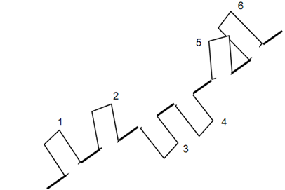
For a six cylinder 4-storke engine along cylinders in line and reciprocating parts and connecting rods identical, the cylinders should be spaced at α= 4π/6 = 120o . The cranks are arranged in three pairs of angular spacing of 120o. Such a crank and shaft arrangement is illustrated in Figure 12.

The primary forces and moments are balanced. Centre line pairs of 1, 6 ; 2, 5 and 3, 4 are parallel. The firing order shall be 1, 2, 3, 6, 5, 4.