Dynamic Magnifier:
DM stands for the dynamic magnifier. It based on the frequency ratio ( ω / ωn ) and damping factor. This is dimensionless.

(i)

(ii)
Likewise DM = X / xst
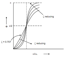
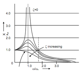
The frequency ratio vs phase angle and frequency ratio vs dynamic magnifier diagrams are illustrated in Figure 2. The following observations can be made based on these diagrams:
(i) The dynamic magnifier varies among nearly zero at very high frequency ratio to more than 1 at resonance.
(ii) For very low damping factor the dynamic magnifier is very large at resonance ? (ω/ ωn = 1) closely equivalent to infinity. But as the damping factor enhances this value drop. That means damping in the system needs to play a role at the resonance. The systems that operate near the resonance must have high amount of damping to drop amplitude or thereby stresses.
(iii) For frequency ratio >2, dynamic magnifier is < 1 and keeps on dropping as frequency ratio increases.
(iv) For low damping phase angle is less than 90o for ω / ωn < 1 and φ ≥ 90 for ω/ ωn > 1 . For ω / ωn = 1 , φ = 90o.
(v) For δ = 0.707, φ is linear for ω / ωn ≤ 1.
The regular solution of the differential Equation (1) is given by following
x = X ′ e-δ ωn t cos (ωd t + φ′) + X sin (ωt - φ) -----------(5)
The first part of the solution is the CF and dies out in a little amount of time that may be few seconds. It is called transient part of the solution. The second part of the solution shows the steady state solution and mass vibrates because of this as long as exciting force activates the system. While the system vibrates if is subjected to fatigue stresses. Hence, larger damage is done to the system because of the larger number of stress because of fatigue loads. The transient solution is not for practical significance and generally we deal with steady state solution as it causes more damage to the system.