Ward and Mellor Extensions
Mellor and Ward extend basic structured analysis notation to accommodate the following demands imposed through a real-time system that are given below:

The data object that is input or output from a process on a continuous basis

A transformer of control or events which accepts control and input and produces control as output
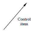
A control item or event which takes on a Boolean or discrete value; the arrowhead indicates the direction of data flow

A repository of control items that are to be stored for use through one or more processes
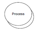
Multiple equivalent instances of the same process; used when multiple processes are created in multitasking system
Figure - Extended structured analysis notation for real-time systems developed by Ward and Mellor
By the significant percentage of real-time application the system must monitor time continuous information generated through some real world procedure. Example for a real time test monitoring system for gas turbine engines might be needed to combustor temperature, monitor turbine speed and a variety of pressure probes on a continuous basis.
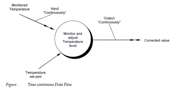
The Conventional data flow notation does not make a distinction among discrete time and data - continuous data. The extension to basic structured analysis notation which is shown in figure gives a mechanism for representing time-continuous flow and a single headed arrow in used to indicate discrete data flow. The figure monitored temperature is measured continuously although a single value for temperature set- point is also provided. Process shown in figure produces a time-continuous output corrected value.
The distinction ion among time and discrete continuous data flow has very important implication for both the system engineer and the software designer. In the duration the creation of the system model a system engineer will be better able to isolate those processes that may be performance critical it is likely in which the input and output of time-continuous data will be performance sensitive. As the implementation or physical model is created the designer must build a mechanism for collection of time-continuous data. Clearly the digital system collects data in a quasi-continuous fashion using methods like as high-speed polling. This notation indicates where analog to digital hardware will be needed and which transforms are likely to demand high-performance software.
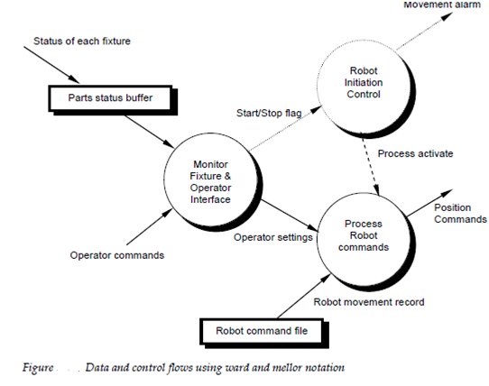
In the conventional data flow diagrams event or control flows are not represented explicitly. In fact the analyst is cautioned to exclusively exclude the representation of control flow from the data flow chart. This exclusion is overly restrictive when real-time applications are assumed and for this reason a specialized notation for representing control processing and event flows has been established. By Continuing the convention established for data flow diagrams data flow is represented using a solid arrow. Control flow moreover is represented using a shaded arrow or dashed. The procedure which handles only control flows is called a control process is same represented using a dashed bubble.
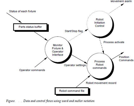
The Control flow can be input straight to a conventional procedure or into a control procedure. In the Figure describe processing and control flow as it would be represented using Mellor and Ward notation. The figure describes a top-level view of data and control flow for a manufacturing cell. As elements to be assembled through a robot are placed on fixtures a status bit is group within an elements status buffer a control store which indicates the absence or presence of each an elements. Even information contained within the parts status buffer is passed as a bit string to a procedure operator interfaces and monitor fixture. The procedure will read operator commands only when the bit string, control information, indicates in which all fixtures include components. An event flag, start or stop flag is sent to robot initiation control, a control process which enables although command processing. Other data flows happen as a consequence of the procedure activate event which is sent to process robot commands.
In some conditions multiple instance of the similar control or data transformation procedure may occur in a real-time system. This process can occur in a multitasking environment when tasks are spawned as a result of external events or internal processing. Example for a number of part status buffers may be monitored so that hard robots can be signaled at the appropriate time. In further, each and every robot may have its own robot control system. The Mellor and Ward notation used to represent multiple equivalent instances of the similar process which is describe in figure.
