Entity-Relationship Diagrams
The object-relationship two of a kind is the cornerstone of the model. Pairs can be presented graphically using the entity relationship diagram ERD 5 the ERD was commonly proposed through Peter Chen [CHE77] for the design of relational database systems and has been extended by others. A group of primary components is identified for the ER: data attributes, objects, relationships and several type indicators. The main purpose of the ERD is to represent data objects and their relationships.

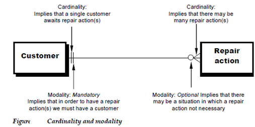
Data objects are represented through a labeled rectangle. The Relationships are indicated with a labeled line connecting objects. By some variations of the ERD the connecting line contains a diamond which is labeled with the relationship connection among relationships and data objects are building using a variety of special symbols which indicate modality and cardinality.
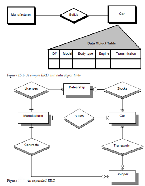
The relationship among manufacturer and data objects card would be represented as shown in the Figure 1. One manufacturer established one or many cars. given the circumstance implied through the ERD the specification of the data object car see the data object table by examining the symbols at the end of the connection line among objects it can be seen that the modality of both occurrences is mandatory the vertical lines

By expanding the model we present a grossly oversimplified ERD Figure 1 of the distribution part of the automobile business. New data objects dealership and shipper are introduced. In addition new relationship contracts, licenses transports and stocks indicate how the data objects controlled in the ERD would have to be established according to the rules introduced previously in this chapter.
In addition to the basic ERD notation introduced in the Figures 1 and 2 the analyst can represent data object type hierarchies. In various instances a data object hierarchies. In various instances a data object may really represent a category or class of information example for the data object car can be categorized as domestic, European, or Asian. The ERD notation which is shown in Figure 3 represents this categorization in the form of a hierarchy.
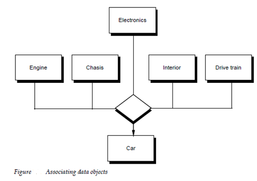
ERD notation also gives a mechanism which represents the associatively among objects. The associative data object is represented which is shown in Figure 4. In the figure the data objects which model individual subsystem are every association with the data object car.

The Data modeling and the entity relationship diagram provide which analysis with a concise notation for examining data within the circumstance of a data processing application. In various cases the data modeling approach is used to create one piece of the analysis model but it can also be used for database design and to support any other requirements analysis method.