Klein's Construction for Determining Velocity And Acceleration Of Slider Crank Mechanism:
There are some special techniques for finding velocity & acceleration of slider in slider crank chain.
Case I
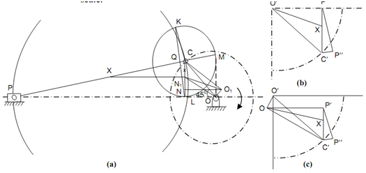
In this case, crank rotation is supposed uniform. The configuration diagram of slider crank chain is illustrated in Figure (a). The method is shown in following steps:
(a) Draw configuration diagram at an appropriate scale.
(b) Extend PC if essential to meet perpendicular to stroke line at M.
(c) Draw a circle with C like centre and CM like radius.
(d) Draw another circle along CP as diameter.
(e) Draw common chord KL of these two circles & extend if essential to meet line of stroke at N. OCQN is acceleration polygon.
(f) NO provides acceleration of piston at a scale equivalent to ω2 × configuration scale.
Proof
In the acceleration polygon OCQN
OC → Centripetal acceleration of C,
CQ → Centripetal acceleration of P associated to C,
QN → Tangential component of acceleration, and
NO → Acceleration of piston.
Connect K with P & C. The triangle CKP & CQK are same

But CK = CM
Hence,

The acceleration according to the methods described earlier has been drawn in Figure (b). The acceleration polygon o′ c′ p″ p′ appears to be likewise to OCQN. If ω is angular velocity of crank, VC = OC ω and likewise velocity of piston VP = ω OM.
Also, VPC = ω CM
Thus, it shows that CQ represents centripetal acceleration  to the scale ω2 × configuration scale. Hence, these two polygons are likewise and ON define acceleration of the piston to the above indicated scale. For a point X on the linking rod, draw a line by X parallel to the line of stroke to intersect CN at x & acceleration of x is illustrated by 'ox'.
Case II
In this case, crank rotates & contains angular acceleration. The acceleration polygon is reproduced in Figure (c). The point Q is finding out in the similar way like in Case I. From O, draw a line perpendicular to CO and plot tangential acceleration OO1. Join C with O1. Through O1, draw a line parallel to line of stroke to meet KL & N1. The acceleration polygon is O1 C Q N1 & O1 N1 is acceleration of the piston. For a point X on CP join x (determined in Case I) with O1. This acceleration polygon is likewise to Figure (c).