PA efficiency
Saving energy is a very important thing. But in electronic power amplifiers, as with many other types of hardware, energy conservation translates into lower cost, smaller weight and size, and longer equipment life.
Power input
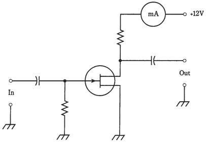
Assume that you connect an ammeter or milliammeter in series with collector or drain of an amplifier and power supply, as shown in the figure given below. While the amplifier is in operation, this meter will have some reading. The reading may appear constant, or it may fluctuate with changes in input signal level

Figure--Connection of a current meter for dc power input measurement.
The direct current collector power input to a bipolar-transistor amplifier circuit is the product of the collector current in amperes, and the collector voltage in volts. Like, for the FET, direct current drain power input is product of drain current and the drain voltage. These power figures can be categorized further as average or peak values.
The direct current collector or drain power input can be high even when there is no signal applied to the amplifier. A class-A circuit operates this way. Actually when a signal is applied to a class-A amplifier, meter reading, and thus the direct current collector or drain power input, will not change compared to value under no signal conditions.
In class-AB1 or class-AB2, there is low current with zero signal, and a higher current with signal.In class-B and class-C, there is no current when there is no input signal. The current, and therefore the direct current power input, increases with the increasing signal.The direct current collector or drain power input is measured usually in watts, the product of amperes and volts. It can be given in milliwatts for low power amplifiers, for high-power amplifiers.
Power output
The power output of the amplifier should be measured by means of a specialized alternating current wattmeter. A direct current ammeter/voltmeter combination will not work. The design of audio frequency and radio-frequency wattmeters is a sophisticated in engineering.
When there is no signal input to the amplifier, there will be no signal output, and therefore power output is zero. The greater the signal input, generally the greater the power output of a power amplifier, up to certain point.
Power output, like direct current collector or drain input, is generally measured in watts. For very low-power circuits, it may be in milliwatts; for high-power circuits it is given in kilowatts.
Definition of efficiency
The efficiency of the power amplifier is ratio of the alternating current power output to the direct current collector or drain power input.
For the bipolar-transistor amplifier, let PC be the direct current collector power input, and Pout be the alternating current power output. For the FET amplifier, let PD be the direct current drain power input. Then the efficiency, eff, is given as follows for the bipolar-transistor circuit, and
eff = Pout /PC
eff = Pout /PD
for the FET circuit. These are ratios, and they will be in between 0 and 1.Efficiency can be expressed as a percentage, so that the formulas become
eff(%) =100 Pout /PC
and
eff(%) =100 Pout /PD
Efficiency versus class
Class-A amplifiers are generally least efficient. The efficiency varies from 25 to 40 %, depending upon nature of input signal and the type of bipolar or field effect transistor used.If input signal is quite weak, such as in the case in a shortwave radio receiver, the efficiency of a class-A circuit is around zero. But in that application, circuit is not working as a power amplifier, and efficiency is not of major importance.
Class-AB amplifiers have better efficiency. A good class-AB1 amplifier may be 35 to 45 % efficient; a class-AB2 amplifier will be a bit better, approaching 60 % with the best designs.
Class-B amplifiers are 50 to 60 % efficient, although some radio frequency PA circuits work up to 65 % or so.
Class-C amplifiers are the best of all. This author has seen designed class-C circuits which are 75 % efficient.
These are not absolute figures, and you should not memorize them as such. It is enough to know ballpark ranges, and which efficiency improves as operating point moves towards the left on curves shown in the figure given below.