Basic bipolar amplifier circuit
In the previous chapters, you saw some circuits that will work as amplifiers. The principle is the same for all the electronic amplification circuits. A signal is applied at some control point, causing greater signal to appear at output.
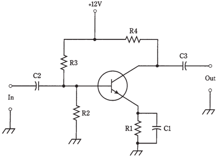
In the figure given below, an NPN bipolar transistor is connected as a common-emitter amplifier. The input signal passes through C2 to base. Resistors R2 and R3 gives bias. Resistor R1 and capacitor C1 allow for emitter to have a direct current voltage relative to ground, while grounded for the signals. Resistor R1 limits the current through transistor. The alternating current output signal goes through capacitor C3. Resistor R4 keeps the alternating current output signal from being short circuited through the power supply.

Figure-- An amplifier using a bipolar transistor.
In this amplifier, the capacitors should have values large enough to allow alternating current signal to pass with ease. But they should not be much larger than the minimum necessary for this reason. If 0.1-µF capacitor will suffice, there is no point in using the 47-µF capacitor. That would introduce the unwanted losses into circuit, and would also make circuit pointlessly expensive to build.
The ideal capacitance values depend on design frequency of amplifier, and on the impedances at input and output. Generally as the frequency and circuit impedance increase, less capacitance is required. At audio frequencies, say 300 Hz to 20 kHz, and at the low impedance, the capacitors can be as large as 100 µF. At radio the frequencies, like 1 MHz to 50 MHz, and having high impedances, values will be only a fraction of the microfarad, down to picofarads at highest frequencies and impedances. The exact values can be determined by the design engineers, working to optimize the performance of circuit in the lab.
The resistor values similarly depend on the application. Typical values are R1 470 ?, R2 4.7 K?, R3 10K?, and R4 4.7 K? for the weak signal, of the broadband amplifier.If circuit is used as a power amplifier, like in a radio transmitter or a stereo hi-fi amplifier, the values of resistors will be different. It might be essential to bias the base negatively with respect to emitter, by using a 2nd power supply with a voltage negative with respect to the ground.