Points In The Rc Quarter-Plane:
The Capacitive reactance can be plotted all along a half-line or ray just as can inductive reactance. The Capacitive and inductive reactance, thought as one, form a real-number line. The point where they link is the zero-reactance point.
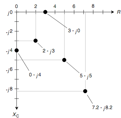
In a circuit having resistance and capacitive reactance, the features are 2-dimensional in such a manner that is analogous to the condition with the RL quarter-plane. The capacitive-reactance and the resistance ray can be positioned end to end at right angles to make the RC quarter-plane (as shown in figure below). The Resistance is plotted horizontally, with raising values toward the right. The Capacitive reactance is plotted downward, with raising negative values as you go down.

Figure: The RC impedance quarter-plane showing five points for particular complex-number impedances.
Complex-number impedances which contain resistance and capacitance can be represented in the form R + jXC; though, XC is never positive. Since of this, scientists frequently write R -jXC, dropping the minus sign from XC and substitution addition with subtraction in the complex-number rendition.
When the resistance is pure, let say, R = 3 ohms, then the complex-number impedance is 3- j0, and this correspond to the point (3, 0) on the RC quarter-plane. You may suspect that 3- j0 is similar as 3 + j0 and that you require not even write the j0 part at all. In theory, both these ideas are accurate. Though, writing the j0 part points out that you are open to the possibility that there may be reactance in the circuit and that you are working in 2-dimensions.
When you have a pure capacitive reactance, let say, XC = -4 ohms, then the complex-number impedance is 0 - j4, and this is at the point (0, -4) on the RC quarter-plane. Again, it is significant, for wholeness, to write the 0 and not just the -j4. The points for 3 - j0 and 0 - j4, & three others, are plotted on the RC quarter-plane as shown in figure below.
In practical circuits, all the capacitors have some leakage conductance. When the frequency goes to zero, which is, when the source is dc, a tiny current will flow as no dielectric is a perfect electrical insulator. A few capacitors have almost no leakage conductance, though none are completely free of it. On the contrary, all electrical conductors have a little capacitive reactance simply since they take place physical space. And hence there is no such thing as a mathematically pure conductor of ac either. The points 3 - j0 & 0 - j4 are idealized.
Recall that the values for XC are reactances, not capacitances. Reactance differs with the frequency in an RC circuit. If you increase or reduce the frequency, the value of XC changes. The higher frequency causes XC to get smaller negatively. A lower frequency causes XC to acquire larger negatively (beyond from zero or lower down on the RC quarter-plane).When the frequency goes to zero, and then the capacitive reactance drops off the bottom of the plane, out of sight. In this situation you have two plates or sets of plates containing opposite electric charges but no "action."