Write some notes for the gauss-seidel method, Electrical Engineering

Assignment Help:

Write Some Notes for the Gauss-Seidel Method?

1.  Equation below is used to calculate the voltage at each busbar in turn, always using the most up to date values for the other busbar voltages. For most systems, the voltages will gradually converge although there are ill conditioned systems in which this convergence fails.

2326_Write Some Notes for the Gauss-Seidel Method.png

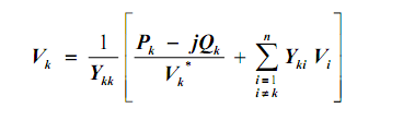
2. When using above equation, remember that (Pk - j Qk) is the power flowing into node   k (generation).    For power flowing out of the node (loads), it is represented by negative power [i.e.  - (Pk - j Qk)].

3.  In the calculation, successively more accurate values of busbar voltage are found. At some stage it is necessary to stop the iterative process as sufficient accuracy has been secured. One may chose to stop the process when no bus voltage changes by more than 0.1% in per unit terms. The calculated voltages are then applied to the network to work out the active and reactive power powers at all busbars.

4.  The Gauss-Seidel method is at times slow to  converge and an acceleration factor can often be usefully applied. The change to the bus voltage in complex form is calculated and then multiplied by an acceleration factor before the new bus voltage value is calculated. The acceleration factor may range up to 2 and is largely a function of the network.  A value of 1.6 is widely used. If a value less than 1.0 is chosen, this may help an otherwise divergent system to converge.

5.  In order to apply the method one of the generator busbars must be specified as having a fixed voltage with the power unknown. This is referred to as the reference or slack busbar and takes up power which is equal to the difference between the specified generation and the sum of the loads plus losses.

6. At any busbar, the active power (P) and reactive power (Q) may be specified and the voltage magnitude and angle are calculated. Such busbar is termed a PQ busbar. If the active power and voltage magnitude are specified, the reactive power and voltage angle are calculated. Such a busbar is known as a PV busbar and is appropriate for generation busbar. 

7.  The Gauss-Seidel method is simple in approach, however, other methods that offer certain advantages are available such as the Newton-Raphson method and the fast decoupled load flow. The latter is almost an industry standard.


Related Discussions:- Write some notes for the gauss-seidel method

TRIAC, what are the electrical characteristics of TRIAC?

what are the electrical characteristics of TRIAC?

Determine the voltage at the load terminals, Two single-phase 60-Hz sinusoi...

Two single-phase 60-Hz sinusoidal-source generators (with negligible internal impedances) are supplying to a common load of 10 kW at 0.8 power factor lagging. The impedance of the

3-phase bridge inverter, 3-phase  Bridge Inverter In 3-phase bridge in...

3-phase  Bridge Inverter In 3-phase bridge inverter six thyristors an six diodes are used as shown in figure  a capacitor at input terminal is connected so that the input volta

Digital ecectronics, DISIGN A FENITE STATE MACHINE TO DETECT THE SEQUENCE 1...

DISIGN A FENITE STATE MACHINE TO DETECT THE SEQUENCE 10110

Explain limit signal spectrum to prevent aliasing, Explain Limit Signal Spe...

Explain Limit Signal Spectrum to Prevent Aliasing? The sampling frequency should at least be two times that of the highest frequency in the incoming signal to avoid aliasing. T

Dual trace and dual beam cro, what is difference between dual trace and dua...

what is difference between dual trace and dual beam cro?

Sectoral overview and enabling framework, Sectoral Overview and Enabling Fr...

Sectoral Overview and Enabling Framework Previously, you have studied about several Acts and Policies relevant to the power sector, their aims, main features and implications

BASIC ELECTRICLE, kindly tell me which text book is usefull forlearn the ba...

kindly tell me which text book is usefull forlearn the basic electricle.

Single sinusoid, Power up the "TIMS" unit by using the switch at the back. ...

Power up the "TIMS" unit by using the switch at the back. Connect the Pico Virtual Instrument (PicoScope) to the PC as per Appendix 1 On the "TIMS" unit, connect the 2 kHz (s

Write Your Message!

Captcha
Free Assignment Quote

Assured A++ Grade

Get guaranteed satisfaction & time on delivery in every assignment order you paid with us! We ensure premium quality solution document along with free turntin report!

All rights reserved! Copyrights ©2019-2020 ExpertsMind IT Educational Pvt Ltd