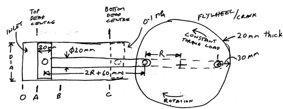
From A to B the inlet valve is open and the steam pressure increases linearly from 0.1000 MPa absolute to 15.00 MPa absolute, 1000°C.
The inlet valve closes and from B to C the steam expands isentropically and adiabatically to the end of the stroke, where the steam pressure is 0.1000 MPa.
The pressure on the crank side of the piston is always 0.1000 MPa.
On the return stroke the exhaust valve is open, so the pressure on both sides of the piston is 0.1000 MPa.
The distance from A to B is 10 + DD/10 mm.
At top dead centre (top of stroke) the distance OA is 10 + BB/10 mm.

For the steam engine given in the above diagram determine the forces on each of the components when the engine is running at constant revolutions per minute (angular velocity at the beginning and end of each revolution is the same but varies during the revolution). Determine these forces at increments of 1 degree of the flywheel position and plot all forces for 1 revolution of the flywheel. Plot the angular velocity of the flywheel. Use the steam tables for your steam calculations.
Make the following assumptions:
(a) All components are made of steel with a density of 7800 kg/m3.
(b) Assume the piston and rod are solid steel pieces (not hollow).
(c) Flywheel speed is 500 RPM when the piston is at top dead centre.