Working of an astable multivibrator, Electrical Engineering

Assignment Help:

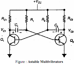
Q. With the help of a npn transistor circuit and wave forms explain the working of an astable multivibrator

In astable multivibrator both transistors are coupled to each other through capacitors as shown in the circuit diagram. Whichever transistor is off at any moment cannot remain off indefinitely; its base will become forward biased as that capacitor charges towards +5 volts.

1238_working of an astable multivibrator.png

Once that happens, that transistor will turn on, thereby turning the other one off. If we pick a moment when Q1 has just turned off and Q2 is on, then the left end of C2 is at -5 volts. This negative voltage decreases as C2 charges through R2 towards +5 volts. However, the moment C2 charges enough to provide forward bias to the base of Q1, Q1 turns on and the 5 volt drop in Q1's collector voltage is coupled through C1 to the base of Q2. This turns Q2 off at once. As we saw in the previous experiment, the time that Q1 remains on and Q2 remains off is 0.693RC, which for the component values shown here is about 1 second.

Now Q2 is held off while C1 charges through R1, until Q2's base becomes forward biased. At that point the transistors switch states again and the whole thing starts over. There is no stable state where the circuit can come to rest, so this circuit is known as an astable multivibrator.

The time Q2 remains off is set by R1 and C1, just as the time Q1 remains off is set by R2 and C2. For our circuit, the components are of the same values on each side, so the timing will be the same on each half of the cycle. This is not required; the two halves of the circuit can have totally different time intervals. They actually operate independently of each other, even though they work together.

Since this particular circuit will spend about 1 second on each half cycle, the total cycle time, or period, is about 2 seconds. The operating frequency of the circuit is the reciprocal of the period, or 0.5 Hz.


Related Discussions:- Working of an astable multivibrator

Show procedure of divide the decimal number by 2, Q. Show procedure of divi...

Q. Show procedure of divide the decimal number by 2? For this procedure (method), divide the decimal number by 2, if the remainder is 0, on the side write down a 0. If the rema

Explain the signals hold and sid, Explain the signals HOLD, READY and SID ...

Explain the signals HOLD, READY and SID HOLD indicates that a peripheral such as DMA controller is requesting the use of address bus, data bus and control bus. READY is used to

Amplifier, what is one common applicable for CB amplifier

what is one common applicable for CB amplifier

Ampere''s theorem, The    French    scientist,    Ampere,    (1775- 1836), ...

The    French    scientist,    Ampere,    (1775- 1836), conducted a series of experiments on the force between current carrying conductors. He found that: force per metre of wire (

Find load resistance and voltage, Q. Find load resistance and voltage? ...

Q. Find load resistance and voltage? Let the amplifier block be connected to a current source at the input terminals, as shown in Figure(a), and to a load resistance R L at it

Explain the block diagrtam of d.c. voltmeter , Q.   Explain the block diagr...

Q.   Explain the block diagrtam of D.C. voltmeter with direct coupled amplifier. Sol. D.C, voltmeter with direct coupled Amplifier         The D.C. electronic voltmeters

Logic Gates, A former employs a servant to look after his form house. He in...

A former employs a servant to look after his form house. He instructs the servant to keep a watch on his goat. So that he does not harm the kitchen garden, when the entrance-door

DC machines, what are the functions of interpolar winding and compensating ...

what are the functions of interpolar winding and compensating winding?

Covert analog signal into digital signal, Covert Analog Signal into Digital...

Covert Analog Signal into Digital Signal A strain gauge is used in Wheatstone Bridge configuration. The output from the Wheatstone Bridge varies from zero to a maximum strain

Calculate the ratio v/i for an ideal diode, Q. Assuming the diode to obey I...

Q. Assuming the diode to obey I = IS (e V/0.026 -1), calculate the ratio V/I for an ideal diode with I S = 10 -13 A for the applied voltages of -2,-0.5, 0.3, 0.5, 0.7, 1.0, and

Write Your Message!

Captcha
Free Assignment Quote

Assured A++ Grade

Get guaranteed satisfaction & time on delivery in every assignment order you paid with us! We ensure premium quality solution document along with free turntin report!

All rights reserved! Copyrights ©2019-2020 ExpertsMind IT Educational Pvt Ltd