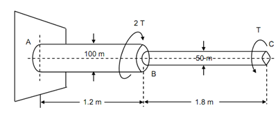
What is the net angle of twist at the free end:
The stepped steel shaft illustrated in Figure is subjected to a torque (T) at the free end and a torque (2T) in the opposite direction at the junction of the two sizes.
What is the net angle of twist at the free end, if the maximum shear stress in shaft is limited to 70 N/mm2?
Suppose the modulus of rigidity to the 0.84 × 10⁵ N/mm2.

Solution
Torque at C = T (anticlockwise)
Torque at B = 2T (clockwise)
Maximum shear stress, τm = 70 N/mm2
G = 0.84 × 10⁵ N/mm2
Assume θ be the angle of twist at C.
Free Body Diagram
A reaction torque shall be induced at section A. Consider this torque be TA clockwise. Then total torque should vanish for equilibrium, thus,
TA + TB - TC = 0
∴ TA = TC - TB = T - 2T = - T
which means torque at A is equal to T in magnitude but opposite the supposed clockwise direction. TA is equal to T anticlockwise as illustrated in free body diagram of Figure .
Figure: Free Body Diagram
The situation is that the equal torques T (but opposite in direction behaves on two portions). The similar magnitude of torque in BC shall induce higher stress than in AB because of diameters as illustrated in Figure. Hence, T should be determined from the portion BC.
T = (π /16) τm d 3 = (π /16) × 70 × (50)3 = 17.2 × 10⁵ Nmm
J AB= (π /32 )× (100)4 = 982 × 105 mm4
J BC = (π/32 ) × (50)4 = 6.14 × 105 mm4
The angle of twist is the difference of twist of C w.r.t. B and the twist of B with respect to A. (As two are in opposite directions).
θBC = T LBC / G J BC (anticlockwise)
θ AC= T LAB / GJ AB (clockwise)
θ=θAC = (T /G) [LBC/ J BC - LAB / J AB ] (anticlockwise)
= (17.2 × 10⁵ /0.84 × 105)[ (1.8 × 10³/ 6.14 × 10⁵ ) - (1.2 × 10³ / 98.2 × 10⁵) ]?
= 20.5 [0.293 - 0.0122] × 10- 2
= 0.058 rad. = 3.3 deg.
or θ = 3o 18′