What is frequency translation and product modulation, Electrical Engineering

Assignment Help:

Q. What is Frequency Translation and Product Modulation?

The basic operation needed to build modulators is the multiplication of two signals. Whenever sinusoids are multiplied, frequency translation takes place. Figure 14.2.1(a) shows a product modulator, which multiplies the signal x(t) and a sinusoidal carrier wave at frequency fc to yield

2180_What is Frequency Translation and Product Modulation.png

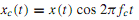
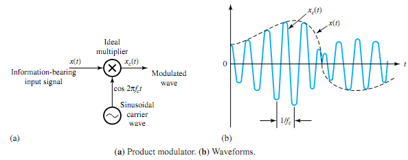
Choosing x(t) to be a low-pass signal with bandwidth W << fc, Figure (b) depicts the relationship between xc(t) and x(t). The modulated wave xc(t) can now be seen to have a bandpass spectrum resulting from frequency translation, which will be explained later. If x(t) contains a sinusoidal component Am cos 2πfmt, multiplication by a sinusoidal carrier wave cos 2πfct with fc >> fm yields

1940_What is Frequency Translation and Product Modulation1.png

Waveforms of the signal, the carrier wave, and the product, as well as their respective line spectra, are shown in Figure. Notice that the low frequency fm has been translated to the higher frequencies fc ± fm.

Next, let us consider an arbitrary low-pass signal x(t) with the typical amplitude spectrum of Figure. The amplitude spectrum of the modulated wave xc(t) will now have two sidebands (lower and upper sidebands), each of width W on either side of fc, as illustrated in Figure. Thus, we have a signal that can be transmitted over a bandpass system with a minimum bandwidth of which is twice the bandwidth of the modulating signal. This process is then known as double-side band modulation (DSB). Either the lower or the upper sidebandmay be removed by filtering so as to obtain single-sidebandmodulation (SSB) with B=W, if the bandwidth needs to be conserved.

1894_What is Frequency Translation and Product Modulation2.png

By choosing the carrier frequency fc at a value where the system has favorable characteristics, the frequency translation by product modulation helps in minimizing the distortion and other problems in system design.


Related Discussions:- What is frequency translation and product modulation

Basic building block of a block diagram, The mathematical relationships of ...

The mathematical relationships of control systems are usually represented by block diagrams, which show the role of various components of the system and the interaction of variable

Ac netwoks, hello look for someone that could do i lab report form me on ac...

hello look for someone that could do i lab report form me on ac network, the report is due tonight at 12:00 so only have 8 hours left wondering if anyone is interested in do it? ca

3-phase bridge inverter, 3-phase  Bridge Inverter In 3-phase bridge in...

3-phase  Bridge Inverter In 3-phase bridge inverter six thyristors an six diodes are used as shown in figure  a capacitor at input terminal is connected so that the input volta

Dc motors, costruction and working of dc motor

costruction and working of dc motor

What do you maen by debugger, What do you maent by Debugger? Debugger:...

What do you maent by Debugger? Debugger: This is a program that allows user to debug and test programs. All computers with microprocessor kits give debugging facility. To not

Find the t-domain forced response in glc parallel circuit, Consider a GLC p...

Consider a GLC parallel circuit excited by i(t) = Ie st in the time domain. Assume no initial inductive current or capacitive voltage at t = 0. Draw the transformed network in the

Performance mapping & implementation plan - power supply, Importance Perfor...

Importance Performance Mapping & Implementation Plan - Power Supply Another data presentation device in which several managers find appealing is the significance-performance m

Superposition principle of linear modulation method, Q. Let m 1 (t) and m 2...

Q. Let m 1 (t) and m 2 (t) be two message signals, and let u 1 (t) and u 2 (t) be the corresponding modulated versions. (a) When the combined message signal m 1 (t) + m 2 (t) DS

Dc machines, explain dynamically induced emf and derive expression for it

explain dynamically induced emf and derive expression for it

Discuss the closed-loop behavior, Q. Discuss the closed-loop behavior? ...

Q. Discuss the closed-loop behavior? Consider an elementary feedback control system, as shown in Figure, with H = 1. The output variable c and the input e to the direct transmi

Write Your Message!

Captcha
Free Assignment Quote

Assured A++ Grade

Get guaranteed satisfaction & time on delivery in every assignment order you paid with us! We ensure premium quality solution document along with free turntin report!

All rights reserved! Copyrights ©2019-2020 ExpertsMind IT Educational Pvt Ltd