What do you mean by amplifier block, Electrical Engineering

Assignment Help:

Q. What do you mean by Amplifier block?

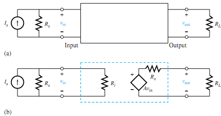
An amplifier can be modeled as a two-port device, that is, a box with two pairs of terminals designated as input and output, as shown in Figure (a). The circuit model of the amplifier block shown in Figure (b) is developed on the basis of the following considerations:

1. Since, for most amplifiers, the input current is proportional to the input voltage, the input terminals in the model are connected by a resistance Ri, known as the input resistance of the amplifier.

2. Since an amplifier delivers electric power (to a speaker, for example), the output current can be represented by its Thévenin-source model. The Thévenin resistance Ro is known as the output resistance and the Thévenin voltage is a dependent voltage source Avin, where A is called the open-circuit voltage amplification.

Thus, the amplifier block is a linear circuit block in which the output is proportional to the input, and the amplifier is characterized by the three constants Ri,Ro, and A. The input and output resistancesmay be generalized to input and output impedances in ac systems. The advantage of the model is that all internal complexities are summarized in the three constants, thereby simplifying the analysis of electric systems with amplifiers. Power-supply connections are usually not shown in circuit diagrams since they would only clutter up the drawing. It is assumed, however, that there are always connections to some power source in order to bring in the power necessary to run the amplifier.

158_What do you mean by Amplifier block.png


Related Discussions:- What do you mean by amplifier block

Any number system to decimal conversion , Any number System  to Decimal Co...

Any number System  to Decimal Conversion To convert a number in any number system to its  equivalent  decimal number, simply multiple each  digit of the number  with its  posi

Briefly explain single mode and multimode fibres, Briefly explain single mo...

Briefly explain single mode and multimode fibres The optical fibres were categorized within two according to the number of modes it passes as: • Single mode fibres • Multi mode

Voltage doubler, Voltage Doubler: The network of Fig. is a half wave v...

Voltage Doubler: The network of Fig. is a half wave voltage doublers. During the positive voltage half cycle across the transformer, secondary diode D 1 conducts, charging ca

Draw the circuit of battery having of three cells in series, One battery ha...

One battery having of three cells in series. External resistance is 5 Ω E.m.f each cell is 1.5V and internal resistance is 0.2?. Measure the current flow and draw the circuit.

Explain medium length lines, Explain Medium length lines? Medium length...

Explain Medium length lines? Medium length lines cover lines in the range of 50 to 150 miles (80 to 240 km). Due to the increased length of the line, the shunt capacitance of t

Fsk scheme, Question: (a) An FSK Scheme is used in a wireless transmi...

Question: (a) An FSK Scheme is used in a wireless transmission with the data bits 1011010. With the help of a labeled diagram, describe in detail the final output of the MSK

Determine the ratio of starting torque to full-load torque, A three-phase, ...

A three-phase, 400-V, wye-connected induction motor takes the full-load current at 45 V with the rotor blocked. The full-load slip is 4%. Calculate the tappings k on a three-phase

Get the equivalent inductance at terminal in circuit, Get the equivalent in...

Get the equivalent inductance at terminal in circuit: Acquire the equivalent inductance at terminal AB in circuit shown in Figure. Solution Inductances also follow the

Second quadrant or class b chopper, Second Quadrant or Class B Chopper ...

Second Quadrant or Class B Chopper Class B  chopper  is shown in figure in this  type of  chopper load  must contain  a dc source E ( may  be battery or a DC motor)  and induct

Give a brief description of integrating circuits, Q. Give a brief descripti...

Q. Give a brief description of integrating circuits ? Integration is a summation of area. An integrating circuit produces an output voltage which is proportional to the area en

Write Your Message!

Captcha
Free Assignment Quote

Assured A++ Grade

Get guaranteed satisfaction & time on delivery in every assignment order you paid with us! We ensure premium quality solution document along with free turntin report!

All rights reserved! Copyrights ©2019-2020 ExpertsMind IT Educational Pvt Ltd