What do you mean by counters, Electrical Engineering

Assignment Help:

Q. What do you mean by Counters?

The shift register can be used as a counter because the data are shifted for each clock pulse. A counter is a register that goes through a predetermined sequence of states when input pulses are received. Besides, computers, timers, frequency meters, and various other digital devices contain counters for counting events.

There are what are known as ripple (asynchronous), synchronous, and ring counters. In ripple counters, the output of each flip-flop activates the next flip-flop throughout the entire sequence of the counter's states. In a synchronous counter, on the other hand, all flip-flops are activated (triggered) simultaneously through a master clock connected to the clock inputs of all flip-flops. In a ring counter, as in a synchronous counter, all flip-flops are triggered simultaneously. However, the output of each flip-flop drives only an adjacent flip-flop. A single pulse propagates through the ring in a ring counter, whereas all remaining flip-flops are at the zero state.

1445_What do you eman by Counters.png

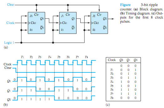
Figure (a) shows a block diagram of a 3-bit ripple counter using JKFFs. Notice from the timing diagram shown in Figure (b) that the output Q0 of the leftmost flip-flop will change its state at every clock pulse if the clear signal equals zero. The output Q1, controlled by Q0, will change its state every time Q0 changes from 0 to 1. Similarly Q2 is controlled by Q1. Figure (c) shows the outputs for the first 8 clock pulses. Observe that a 3-bit counter will cycle through 8 states, 000 through 111. An n-bit ripple counter, in general, will cycle through 2n states; it is known as a divide-by-2n counter or modulo-2n binary counter. Taking the outputs from Q2 Q1 Q0, the counter becomes an up-counter; taking the outputs from ¯Q2 ¯Q1 ¯Q0, the counter becomes a down-counter, which counts down from a preset number. Asynchronous ripple counters are available as MSI packages.


Related Discussions:- What do you mean by counters

Dc circuits, Dc Circuits: In this unit, you have learned about methods...

Dc Circuits: In this unit, you have learned about methods of network analysis which are general in nature such as KCL, KVL, Nodal and Mesh analysis. These general methods may

Perform octal subtraction, Q. Do as directed. a) Hexadecimal addition: ...

Q. Do as directed. a) Hexadecimal addition: 101 + ABC b) (43.25) 10-(89.75) 10 using 1's Complement c) Octal Subtraction 123-777 d) (123)6 + (435)6 = ( ? )6 e) ABC

Calibration and testing of energy meters, Calibration and Testing of Energy...

Calibration and Testing of Energy Meters and Meter Laboratory Energy meters form a vital instrument of revenue realization for the distribution utilities. Based on the meter r

Name the flag available in status register of 8086, What are the different ...

What are the different flag available in status register of 8086? There are Six flags are present. They are, AF - Auxiliary Carry Flag CF - Carry Flag OF - Ove

Voltage doubler, Voltage Doubler: The network of Fig. is a half wave v...

Voltage Doubler: The network of Fig. is a half wave voltage doublers. During the positive voltage half cycle across the transformer, secondary diode D 1 conducts, charging ca

Successive approximation adc, Successive approximation ADC One method ...

Successive approximation ADC One method of addressing digital ramp ADC's shortcomings is so-called successive approximation ADC. Only change in this design is a very special c

Find out form factor and peak factor, Find out Form factor and Peak factor:...

Find out Form factor and Peak factor: For the output of full wave rectifier, find out (a) RMS value, (b) Average value, (c) Form factor, and (d) Peak factor. S

Can you explain about trapeziodal clippers, Q. Can you explain about Trapez...

Q. Can you explain about Trapeziodal Clippers? During The Positive half cycle, the diode D1 will be open circuited and the input appears as the output until, the applied bias v

Mode 2 - boost converter, Mode 2 In this  mode transistor  gets turne...

Mode 2 In this  mode transistor  gets turned off by  the negative output  of PWM  current  flows  through  inductance L diode D then  divide into two  parts one flows through

Write Your Message!

Captcha
Free Assignment Quote

Assured A++ Grade

Get guaranteed satisfaction & time on delivery in every assignment order you paid with us! We ensure premium quality solution document along with free turntin report!

All rights reserved! Copyrights ©2019-2020 ExpertsMind IT Educational Pvt Ltd