Voltage division, Physics

Assignment Help:

Voltage division:

In a series circuit Ohm's law applies for each component.  However, since the current is common to all components we have:

          V1 = IR1,  V2 = IR2,  V3 = IR3

          Therefore  V1 ∝ R1,  V2 ∝ R2,  V3 ∝ R3

          i.e.    Vn ∝ Rn

Hence the voltage drops across each resistor can be calculated from the ratio of the resistance values.

694_VOLTAGE DIVISION.png

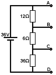
It should also be noted, that for any given applied voltage we may derive any smaller voltages we wish by inserting resistors of the appropriate values in series. The following example shows how voltages of 8V, 4V and 24V can be derived from a 36V supply.

RTOTAL = 12 + 6 + 36 = 54W

  54Ω = 36V and 1Ω = 36/54V

  12Ω = 36/54 ´ 12 = 8V across AB

and  6W = 36/54 * 6 = 4V across BC

and  36Ω = 36/54 ´ 36 = 24V across CD


A device which employs voltage division and which is commonly used in electrical and electronic circuits is the potential divider.  Here two or more resistors are used to divide a given input voltage to achieve a specified output voltage.  See diagram.

220_VOLTAGE DIVISION1.png

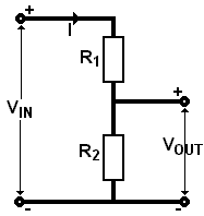
The potential divider is also known as a voltage divider or scaling circuit.

Note that if current is drawn from the output then the effective resistance of the circuit changes and the output voltage vOUT changes.


Related Discussions:- Voltage division

Inertial frame of reference, Inertial Frame of Reference : If in a given sy...

Inertial Frame of Reference : If in a given system a free object does not experience any acceleration or force, the system is called the inertial frame. Any reference frame that mo

Calculate mass of an electron, Calculate mass of an electron accelerated to...

Calculate mass of an electron accelerated to kinetic energy of 2 M eV.

All about bernoulli, write bernoulli,s equation using pressure,energy,and h...

write bernoulli,s equation using pressure,energy,and heads.

Verify the rms potential drops across the three elements, The given circuit...

The given circuit diagram shows a series LCR circuit linked to a variable frequency 230 V source: (a) Verify the source frequency which drives the circuit in resonance. (b) G

Reduce the expression for expected fringe shift, Deduce the expression for ...

Deduce the expression for expected fringe shift in Michelson Morley experiment. Discuss the result of experiment.

What are the advantages of fibre optic communication, What are the advantag...

What are the advantages of fibre optic communication? Advantages of fibre optic communication are as follows: a. Enormous band width Coaxial cable transmission of 500 M

Explain forward bias and reverse bias, Explain briefly, with the help of ci...

Explain briefly, with the help of circuit diagram, how V - I characteristics of a p-n junction diode are obtained ii (i) forward bias, and (ii) reverse bias. Illustrate th

Explain retina, Retina It is inner most and sensitive layer. It receive...

Retina It is inner most and sensitive layer. It receives images of near and far objects.

Calculate the final intensity, Randomly polarized light (such as sun light)...

Randomly polarized light (such as sun light) with intensity of I 0 passes through three polarizers (P 1 , P 2 , P 3 ) consecutively.  P 1 and P 3 are stationary, and their polar

Zone plate, What is a zone plate? How is it constructed? Show that a zone p...

What is a zone plate? How is it constructed? Show that a zone plate behaves like a convex lens. Deduce the expression for its focal length

Write Your Message!

Captcha
Free Assignment Quote

Assured A++ Grade

Get guaranteed satisfaction & time on delivery in every assignment order you paid with us! We ensure premium quality solution document along with free turntin report!

All rights reserved! Copyrights ©2019-2020 ExpertsMind IT Educational Pvt Ltd