Turbine engines cooling :
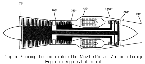
Turbine engines are designed to convert heat energy into mechanical energy. The combustion process is continuous and, therefore, heat is produced. On turbine engines, most of the cooling air must pass through the inside of the engine. If only enough air were admitted into a turbine engine to support combustion, internal engine temperatures would rise to more than 4,000 degrees Fahrenheit. In practice, a typical turbine engine uses approximately 25 percent of the total inlet airflow to support combustion. This airflow is often referred to as the engine's primary airflow. The remaining 75 percent is used for cooling, and is referred to as secondary airflow.
When the proper amount of air flows through a turbine engine, the outer case will remain at a temperature between ambient and 1,000 degrees Fahrenheit depending on the section of the engine. For example, at the compressor inlet, the outer case temperature will remain at, or slightly above, the ambient air temperature. However, at the front of the turbine section where internal temperatures are greatest, outer case temperatures can easily reach 1,000 degrees Fahrenheit.
Cooling Requirements
To properly cool each section of an engine, all turbine engines must be constructed with a fairly intricate internal air system. This system must take ram and/or bleed air and route it to several internal components deep within the core of the engine. In most engines, the compressor, combustion, and turbine sections all utilise cooling air to some degree.
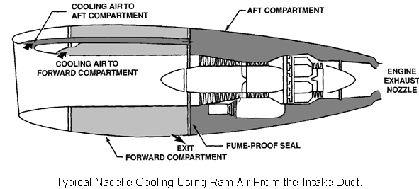
For the most part, an engine's nacelle is cooled by ram air as it enters the engine. To do this, cooling air is typically directed between the engine case and nacelle. To properly direct the cooling air, a typical engine compartment is divided into two sections; forward and aft. The forward section is constructed around the engine inlet duct while the aft section encircles the engine. A seal or firewall separates the two sections.
In flight, ram air provides ample cooling for the two compartments. However, on the ground, airflow is provided by the reduced pressure at the rear of the nacelle. The low pressure area is created by the exhaust gases as they exit the exhaust nozzle. The lower the pressure at the rear of the nozzle, the more air is drawn in through the forward section.