Transformer of distribution, Electrical Engineering

Assignment Help:

Transformer of distribution:

Let be the transformer of distribution of the Face(Figure) 3 connected to the primary between phase a and c of a three-phase network of 23 kV. Both rolling-ups of low voltage are 120 V with the indicated polarities.

Loadsconnected to the secondary are:

L1: Heating, 1.5 kW with a power factor of 1

L2:Drill, 0.5 kW with a power factor of 0.81 lagging.

L3:Pump, 2.53 kW with a power factor of 0.92 lagging

The model of the transformer is of ideal type.

1-Calculate the current phasor of the loadL1.

2-Calculate the current phasor of the loadL2.

3-Calculate the current phasor of the loadL3.

4-Calculate the currentphasor in the primaryof the transformer (entering the positive polarity).

5-Calculate the total apparent power seen in the primary of the transformer.

1383_Transformer of distribution.png

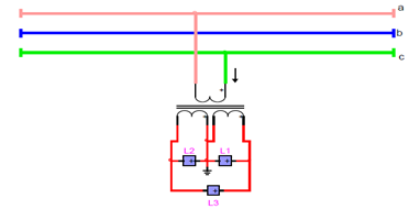
Figure: The transformer of distribution


Related Discussions:- Transformer of distribution

Comparison of analog-modulation systems, Comparison of Analog-Modulation Sy...

Comparison of Analog-Modulation Systems The comparison of analog modulation systems (conventional AM, DSB SC, SSB SC, VSB, FM, and PM) can be based on three practical criteria:

Explain extrinsic semiconductor, Explain Extrinsic Semiconductor. Extr...

Explain Extrinsic Semiconductor. Extrinsic Semiconductor: An intrinsic semiconductor is able to conduct some current even at room temperature but as this is not helpful for t

Microprocessor, highest priority interrupt in 8085 microprocessor

highest priority interrupt in 8085 microprocessor

D.C. generator, I have made a wind turbine with vertical blades. I want to ...

I have made a wind turbine with vertical blades. I want to rotate magnets on the rotor with the coils being stationary.How do I wind the coils and must the magnets be N/S opposite

Clapp oscillator, derivation of frequency of oscillators clapp and derive C...

derivation of frequency of oscillators clapp and derive C effect?

Determine the force, Consider an electromagnet, as shown in Figure, which i...

Consider an electromagnet, as shown in Figure, which is used to support a solid piece of steel and is excited by a coil of N = 1000 turns carrying a current i = 1.5 A. The cross-se

Find the voltage , 1. Find the current through each component, in pola...

1. Find the current through each component, in polar form, using mesh analysis. The source voltages are rms with an angle of 0 degrees. 2. Find the current t

Difference between write-through and write-back caches, The comparison can ...

The comparison can be made out of two feature 1) Performance and 2) Integrity of Data Write through is better in integrity as it will flush for every writes. Write b

Determine the complete response for capacitance, Consider the circuit of Fi...

Consider the circuit of Figure for t> 0 with zero initial conditions, v Th (t) = 1 V (dc), and R Th = 2 ; L = 1 H. Determine the complete response for vC(t) for capacitance value

Write Your Message!

Captcha
Free Assignment Quote

Assured A++ Grade

Get guaranteed satisfaction & time on delivery in every assignment order you paid with us! We ensure premium quality solution document along with free turntin report!

All rights reserved! Copyrights ©2019-2020 ExpertsMind IT Educational Pvt Ltd