Torsional equation , Mechanical Engineering

Assignment Help:

Torsional equation:

Derive the Torsional equation T/J = Π  /R = /L

Or

Derive an expression for the shear stress in shaft subjected to a torque.

Sol.: Assume,

T  = Maximum twisting torque or twisting moment

D = Diameter of shaft

R = Radius of shaft

J  = Polar moment of Inertia

τ= Maximum Permissible Shear stress (Fixed for given material)

G = Modulus of rigidity

θ= Angle of twist (Radians) = angle D'OD L  = Length of shaft.

?= Angle D'CD = Angle of Shear strain


2090_Torsional equation.png

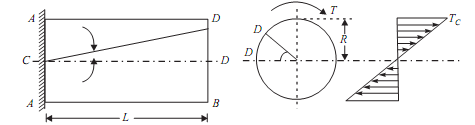
Than Torsion equation is: T/J =   τ/R = G. θ /L

Let the shaft is subjected to a torque or twisting moment 'T'. And hence every C.S. of this shaft will be subjected to shear stress.

Now distortion at the outer surface = DD'

Shear strain at outer surface = Distortion/Unit length tan?         = DD'/CD

i.e. shear stress at the outer surface (tan? ) = DD'/or  = DD'/L           ...(i)

Now DD' = R.θ              or      ?= R .  θ /L    ...(ii)

Now G = Shar stress induced/shear strain produced

G =   τ/(R. θ /L);

or;                                             τ/R = G. θ /L                              ...(A);

This equation is called Stiffness equation.

Hear G,  θ , L are constant for a given torque 'T'. That is proportional to R

If τ r  be the intensity of shear stress at any layer at a distance 'r' from canter of the shaft, then;

1566_Torsional equation1.png

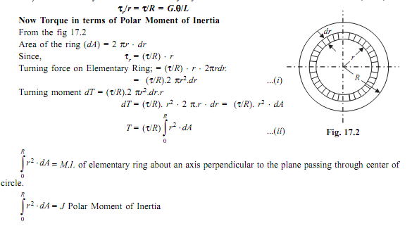
Now from equation (ii) T = ( τ/R)   J

or                                              τ/R = T/J;                                   ...(B)

This equation is called as strength equation

The combined equation A and B; we get

T/J =   τ/R = G.  τ/L

This equation is called as Torsion equation.

From the relation             T/J =   τ/R ; We have  T =   τ.J/R =  τ .ZP

For the given shaft I and R are constants and IP/R is thus constant and is called as POLAR MODULUS(ZP). of the shaft section.

Polar modulus of section is thus measure of strength of shaft in the torsion.

TORSIONAL RIGIDITY or Torsional Stiffness (K): = G.J/L = T


Related Discussions:- Torsional equation

Kleins construction method , How kleins construction method is different fr...

How kleins construction method is different from other type of graphical method

Calculate transmitted force, A machine having a mass of 100 Kg and supporte...

A machine having a mass of 100 Kg and supported on springs of total stiffness 7.84 x 10⁵ n/m has an unbalanced rotating element which results in a disturbing force of 400 N at a sp

Describe the modes of failure in bearing capacity, Describe the modes of fa...

Describe the modes of failure in bearing capacity. Modes of Failure: Behaviour of foundations subjected to load based on actual observations suggests that the bearing capaci

Velocity acquired by block - system released from rest, Velocity acquired b...

Velocity acquired by block - system released from rest: T wo blocks shown in the figure given below, have masses A = 20N and B = 10N and the coefficient of friction between

Explain internal broaching - types of broaching, Explain Internal Broaching...

Explain Internal Broaching - Types of Broaching Internal broaching operation is adopted for producing internal surface such as holes, keyways and teeth of an internal gear for

Stress plots, Problem:   The following machine component is loaded as s...

Problem:   The following machine component is loaded as shown.  It is fabricated from Al 6061-T6.   Determine the analytical solution to this problem and compare result

Compound shaft, Compoun d shaft: compoun d shaft? How is compound ...

Compoun d shaft: compoun d shaft? How is compound shaft classified?                                                               Sol.: Shaft made up of 2 or more mat

T-section, Ask question #MinimA beam of T-section with flange 300 mm × 30 m...

Ask question #MinimA beam of T-section with flange 300 mm × 30 mm and web 260 mm × 30 mm is subjected to a shear force of 100 kN. Determine the percentage of shear force carried by

What are the technical limitations of screw conveyer, What are the Technica...

What are the Technical Limitations of screw conveyer Technical Limitations: ? Turning limitation of this mechanism Actually the Maximum Turning of U-joint is 18° to 2

Write Your Message!

Captcha
Free Assignment Quote

Assured A++ Grade

Get guaranteed satisfaction & time on delivery in every assignment order you paid with us! We ensure premium quality solution document along with free turntin report!

All rights reserved! Copyrights ©2019-2020 ExpertsMind IT Educational Pvt Ltd