Time and cost analysis, Mechanical Engineering

Assignment Help:

Time and Cost Analysis

This discusses about certain basic activities that must be carried out in a factory to convert raw materials into finished products. These activities broadly are Processing and assembly operations, Material handling, Inspection and testing and Coordination and control.

The machining times for various machining processes and the importance of it is explained.

The machining time in turning (t) is as

t = L + L0 /2 f N

The machining time in milling T in minutes can be calculated as

T = (L × n)/ f Z N minutes

Time for drilling the hole = L/ f N     minutes

Machining Time = Depth of hole to be bored in mm minutes/ N × feed/rev

where, N = No. of revolutions per min. of machine spindle or work.

In boring operation the machining time is calculated the same manner as in turning. It is given by the following relation :

Machining Time = Depth of hole to be bored in mm minutes/ N × feed/rev

where, N = No. of revolutions per min. of machine spindle or work. Machining time for shaping can be calculated as below.

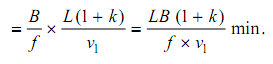
No. of cycles required (n) = Shaping width / Feed per cycle f

= B/f

Machining time = No. of cycles × time required for each cycle

1428_Time and Cost Analysis.png

The machining time (T) in cylindrical grinding can be calculated from the following relationship.

T = (L . P . K )/ ( f . N . t) min .

The total production cost of machined components is made up of the following components : material cost, labour cost, overhead cost, tool cost and cost of percent of the total cost. But the influence of tools on the other costs is considerable. It is often possible that the tool cost is increased but the total production cost is reduced considerably because of the influence of the tool on other aspects of cost.

The costs that go into machining a part can be broken into three categories as Material removal cost, Tool cost and Non-productive cost

Total machining cost = Material removal cost + Tool cost + Non-productive cost. The tool cost is made up of

(a) Tool change cost (TCC) or cost for indexing the insert

(b) Tool regrinding cost (TRC)         

(c)  Tool original cost (TOC)

(d) Tool inventory cost (TIC)

Total tool cost = TCC + TRC + TOC + TIC


Related Discussions:- Time and cost analysis

Characterised punching shear failure in bearing capacity, How can punching ...

How can punching shear failure are characterised in bearing capacity? Punching Shear Failure This mode of failure is characterised by large deformations beneath the footing

Evaluate the springs force necessary to set the brake, A Double shoe brake ...

A Double shoe brake is capable of absorbing a torque of 1400 N-m. The diameter of the brake drum is 350 mm and the angle of contact for each shoe is 100 o . if the coefficient of f

Solids of mechanics, Derive the equation for pure bonding of beam (simply)

Derive the equation for pure bonding of beam (simply)

Purpose of corrosion assessment design, Q. Purpose of Corrosion assessment ...

Q. Purpose of Corrosion assessment design? The purpose of this design guide is to ensure that Material Selection for Steam Assisted Gravity Drainage (SAGD) projects is carried

Plate clutch pressure height-clutch slipping, Plate clutch pressure height ...

Plate clutch pressure height : Check plate clutch pressure leg height by placing the plate clutch pressure on the surface plate. Plate clutch pressure should not tilt on the surfa

Explain about nonconforming material, Q. Explain about Nonconforming Materi...

Q. Explain about Nonconforming Material? If PMI test results indicate that the material or item does not meet the specified composition of the alloy, the subject material/item

Determine the maximum bending stresses, Determine the maximum bending stres...

Determine the maximum bending stresses: A rectangular beam of breadth 100 mm & depth 200 mm is simply supported over a span of 4 m. The beam is loaded with a uniformly distrib

Find out load carried and compressive stress - steel bar, Find out load car...

Find out load carried and compressive stress: The concrete column 300mm x 300mm in section can be reinforced by 10 longitudinal 20mm diameter round steel bars. The column car

Relative velocity in mechanism, how can I determine the relative velocity ...

how can I determine the relative velocity in mechanism

Cantilever beam stress, Dear Engineer! I have an aluminum tube(6061) fixed...

Dear Engineer! I have an aluminum tube(6061) fixed at one end (Cantilever Beam). The length is 180” and the load on the other end is 150 lbs. Question: What size of tubes I s

Write Your Message!

Captcha
Free Assignment Quote

Assured A++ Grade

Get guaranteed satisfaction & time on delivery in every assignment order you paid with us! We ensure premium quality solution document along with free turntin report!

All rights reserved! Copyrights ©2019-2020 ExpertsMind IT Educational Pvt Ltd