Thrust indication:
Although rpm gauges give an indication of the rotational speed of the compressor, they do have one drawback. They do not normally indicate the thrust output or power output of the engine. Any distress within a compressor may cause the engine to have a reduction in thrust output. Some means must be provided, therefore, to indicate the engine's power output. This is done by using an engine pressure ratio system, which is commonly known as EPR.
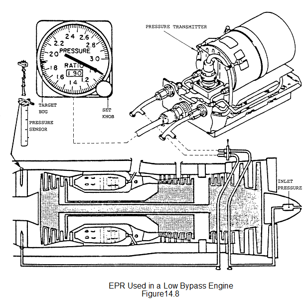
The system consists of pitot type pressure heads located in the engine inlet, which are averaged together and a series of pitot type pressure heads located at the turbine exhaust which are averaged together. Both feed into a pressure ratio transmitter. On a high bypass engine the sensed pressure at the rear of the engine can be the by pass or cold flow or a combined input from both the hot and cold flows.
The transmitter receives the pressure inputs from the inlet, and from the exhaust gas pressure probes. The probes are connected in to a common manifold, thus providing an average gas pressure. Both pressure tubes to the transmitter are provided with water drain traps that must be drained during maintenance checks.
The formula used by the transmitter in determining the EPR
signal is:- EPR = exhaust pressure/inlet pressure
Sometimes it can be expressed by using engine station configuration numbers, i.e. inlet PT2 or Exhaust PT7 (PT= pressure total), therefore EPR can be expressed as:-
PT7/PT2
As EPR is used as a thrust parameter, the flight crew must determine the maximum EPR for the barometric/temperature conditions. Take off EPR or maximum EPR can be determined by checking trim charts for engineers, or take off charts for flight crew. The EPR gauge in Fig. that there is an EPR set knob. Once the EPR target figure has been calculated, then by turning the knob 'a reference target bug can be set at the take off EPR setting. This indicates to the crew the maximum amount of EPR required. Exceeding this figure could possibly overboost the engine. Modern aircraft use aircraft sensors to make this correction and will set the bug for the pilot if required.