Thrust diagrams for the beam, Mechanical Engineering

Assignment Help:

Thrust diagrams for the beam:

Illustrate the shear force, bending moment & thrust diagrams for the beam illustrated in Figure

2140_Thrust diagrams for the beam.png

Figure

Solution

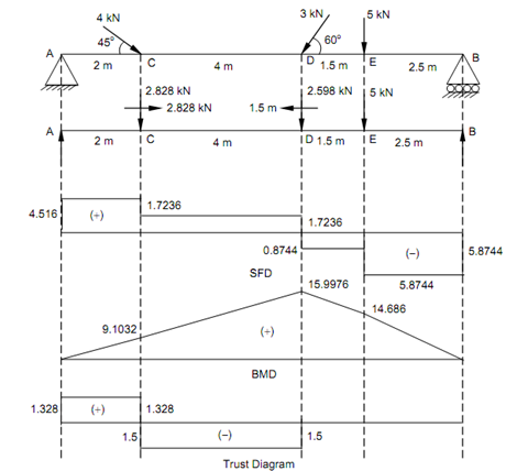
Vertical component of 4 kN at C, = 4 × sin 45o = 2.828 kN ( ↓ )

 Horizontal component of 4 kN at C, = 4 × cos 45o = 2.828 kN ( → )

Vertical component of 3 kN at D, = 3 × sin 60o = 2.598 kN ( ↓ )

Horizontal component of 3 kN at D, = 3 × cos 60o = 1.5 kN ( ← )

Taking moments around B,

RB  × 10 - 5 × 7.5 - 2.598 × 6 - 2.828 × 2 = 0

RB  = 5.8744 kN

RA  = 2.828 + 2.598 + 5 - RB  = 10.426 - 5.8744

RA  = 4.5516 kN

Shear Force (Beginning from the Left End A)

SF at A, FA  =+ 4.5516 kN

SF just left of C, FC  =+ 4.5516 kN

SF just right of C, FC  =+ 4.5516 - 2.828 =+ 1.7236 kN

SF just left of D, FD  =+ 1.7236 kN

SF just right of D, FD  = + 1.7236 - 2.598 = - 0.7844 kN

SF just left of E, FE  =- 0.8744 kN

SF just right of E, FE  =- 0.8744 - 5 =- 5.8447 kN = Reaction at B.

Bending Moment (Beginning from the Right End B)

BM at A and B,          MA = MB = 0

 BM at E, M E  = + (5.8744 × 2.5) = + 14.686 kN-m

BM at D, M D  = + 5.8744 × 4 - 5 × 1.5 = + 15.9976 kN-m

BM at C, M C  = + (4.5516 × 2) = + 9.1032 kN-m  (considering left side)

Maximum Bending Moment

It shall occur at D where SF changes sign.

Thus, M max  = + 15.9976 kN-m

Thrust Diagram

 Let us find out the horizontal reaction at A (being a hinged end).

∑ H = 0

+ H A - 2.828 + 1.5 = 0

∴          H A = 1.328 kN

The section AC is subjected to 1.328 kN (tensile force).

The section CD is subjected to 1.5 kN (compressive force).

∴          (2.828 - 1.328 = 1.5)


Related Discussions:- Thrust diagrams for the beam

Show continuity equation in cylindrical coordinates, Show continuity equati...

Show continuity equation in cylindrical coordinates. Also list the assumptions made. A fluid flow is given by V = xy 2 i - 2yz 2 j - (zy 2 - 2z 3 /3) k Determine acceleration

Describe the term critical insulation thickness, Q. Describe the term ‘Crit...

Q. Describe the term ‘Critical Insulation thickness'. What is its significance? Derive an expression for the critical insulation radius of a spherical system. A bar of square cr

Selection of elctrodes, Q. Describe the Selection of elctrodes? The sel...

Q. Describe the Selection of elctrodes? The selection of a proper electrode for electric arc welding is very important to obtain a sound welded joint of proper strength. The va

Center of Gravity, Determine the Center of Gravity of a thin hollow right c...

Determine the Center of Gravity of a thin hollow right circular cone of height H and radius of the base circle R.

Illustrate process of radiographic examination, Q. Illustrate process of Ra...

Q. Illustrate process of Radiographic Examination? Radiographic examination of welded joints shall be performed when required by the Code or additionally when specified in this

Determine forces in members of cantilever truss, Determine  forces in memb...

Determine  forces in members of cantilever truss: Determine  forces  in  members   B C   and  BD   of   cantilever truss  shown  in  the figure in the figure given below.

Determine the maximum profit value, A company makes two types of sofas, reg...

A company makes two types of sofas, regular and long, at two locations, one in Nottingham and one in London. The plant in Nottingham has a daily operating budget of £45,000 and can

Movement of wire at the signal box, Movement of wire at the signal box: ...

Movement of wire at the signal box: The wire working on railway signal is 5mm in diameter and 300m long. If movement at the signal end is to be 25cm, make calculations for mo

Determine the deflection at free end, Determine the deflection at free end:...

Determine the deflection at free end: For the beam illustrated in Figure, determine the deflection at free end and the maximum deflection. Figure Solution R

Simulate the compression test, This assignment will simulate large deformat...

This assignment will simulate large deformations (nonlinear geometry) and occurrence of necking and buckling due to static tensile and compressive loading of a given elastic-plasti

Write Your Message!

Captcha
Free Assignment Quote

Assured A++ Grade

Get guaranteed satisfaction & time on delivery in every assignment order you paid with us! We ensure premium quality solution document along with free turntin report!

All rights reserved! Copyrights ©2019-2020 ExpertsMind IT Educational Pvt Ltd