System of loads - beam, Mechanical Engineering

Assignment Help:

System of loads -  Beam:

Build the SFD & BMD for 10 m span simply supported beam subjected to a system of loads as illustrated in Figure .

512_System of loads -  Beam.png

Figure

Taking moment around A and equating to zero.

R B   × 10 - 2 × 4 × (6 + (4/2)) - 3 × 8 - 4 × 6 - 5 × 5 - 1.2 × 5 × (5/2) - 1 × 2 = 0

RB = 154 /10 = 15.4 kN

 RA = (1.2 × 5) + 1 + 5 + 4 + 3 + (2 × 4) - RB

RA = 27 - 15.4 = 11.6 kN.

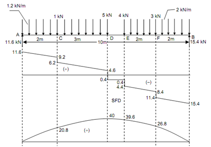
Shear Force (starting from left end) SF at A, FA = + 11.6 kN

SF just left of C, FC = + 11.6 - (1.2 × 2) = + 9.2 kN

SF just right of C, FC = + 9.2 - 1 = + 8.2 kN

SF just left of D, FD = + 8.2 - (1.2 × 3) = + 4.6 kN

SF just right of D, FD = + 4.6 - 5 = - 0.4 kN

SF just left of E, FE = - 0.4 kN

SF just right of E, FE = - 0.4 - 4 = - 4.4 kN

SF just left of F, FF = - 4.4 - (2 × 2) = - 8.4 kN

SF just right of F, FF = - 8.4 - 3 = - 11.4 kN

SF just left of B, FB = - 11.4 - (2 × 2) = - 15.4 kN

Bending Moment

BM at A and B, MA = MB = 0

BM at F, M =+ (15.4 × 2) - (2 × 2 × (2/2)) =+ 26.8 kN m = + 39.6 kN m

BM at E, M =+ (15.4 × 4) - (3 × 2) - (2 × 4 × (2/2)) =+ 39.6 kN m

BM at D, M =+ (11.6 × 5) - (1 × 3) -(1.2 × 5 × (5/2)  = 40 kN m

                                                                  (considering left side)

BM at C, M =+ (11.6 × 2) - (1.2 × 2 × (2/2)) =+ 20.8 kN m

                                                                    (considering left side)

As the SF changes sign at D, the maximum bending moment occurs at D.

Mmax = MD = + 40 kN m


Related Discussions:- System of loads - beam

Foil butt seam welding, Foil Butt Seam Welding This is a modification o...

Foil Butt Seam Welding This is a modification of seam welding, in which thin narrow strips of metal arc introduced between one or both of the circular electrodes and the work p

Evaluate the maximum bending stresses, Evaluate the maximum bending stresse...

Evaluate the maximum bending stresses: A beam of I-section illustrated in Figure is simply supported over a span of 10 m. It carries an uniform load of 4 kN/m over the whole s

Slidercrank, connecting rod AB of length L support a variable compressiv fo...

connecting rod AB of length L support a variable compressiv force F .Drive an expression for the moment of F about the crank axis O in the term of F L r and angle

Surface chemistry and electrochemistry of membranes, explain surfacechemist...

explain surfacechemistry and electrochemistry of membranes?

Evaluation of specific volume of steam - thermodynamics , Evaluation of Spe...

Evaluation of Specific Volume of Steam: Specific volume of steam means the volume which is occupied by unit mass of steam. It is expressed in m3 /kg. Specific volume of steam

How do we adjust throttle free play?, (a) What is the function of a throttl...

(a) What is the function of a throttle valve? Where it is used? (b) How do we adjust throttle free play?

Context level data flow diagram, Context Level Data Flow Diagram In thi...

Context Level Data Flow Diagram In this section, the cell control model conversation in the former section is demonstrated by the data flow diagram as in following figure of co

Assumptions in analysis of simple truss, Assumptions in analysis of simple ...

Assumptions in analysis of simple truss: What are assumptions made in analysis of simple truss? Sol.: The assumptions made in finding out forces in the frame are, (1)

If o ring found to be leaking-oil seal is found be leak, If "o" ring is fou...

If "o" ring is found to be leaking or oil seal is found to be leaking check as mentioned: If "O" ring found to be leaking change "O" rings. If oil seal found to be leaking check o

Write Your Message!

Captcha
Free Assignment Quote

Assured A++ Grade

Get guaranteed satisfaction & time on delivery in every assignment order you paid with us! We ensure premium quality solution document along with free turntin report!

All rights reserved! Copyrights ©2019-2020 ExpertsMind IT Educational Pvt Ltd