Solid-state control of synchronous motors, Electrical Engineering

Assignment Help:

Solid-State Control of Synchronous Motors

 The speed of a synchronous motor can be controlled by changing its supply frequency. With variable-frequency control, two modes of operation are possible: true synchronous mode, employed with voltage source inverters, in which the supply frequency is controlled from an independent oscillator; and self-controlled mode, in which the armature supply frequency is changed proportionally so that the armature field always rotates at the same speed as the rotor. The true synchronous mode is used only in multiple synchronous-reluctance and permanent-magnet motor drives, in applications such as paper mills, textile mills, and fiber-spinning mills, because of the problems associated with hunting and stability. Variable-speed synchronous-motor drives, commonly operated in the self-controlled mode, are superior to or competitive with induction motor or dc-motor variable-speed drives.

Drives fed from a load-commutated current-source inverter or a cycloconverter find applications in high-speed high-power drives such as compressors, conveyors, traction, steel mills, and ship propulsion. The drives fed from a line-commutated cycloconverter are used in low-speed gearless drives for mine hoists and ball mills in cement production. Self-controlled permanent- magnet synchronous-motor drives are replacing the dc-motor drives in servo applications.

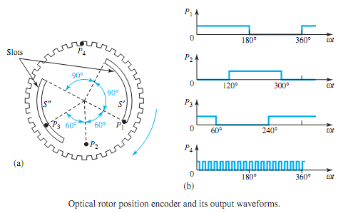
Self-control can be applied to all variable-frequency converters, whether they are voltage- source inverters, current-source inverters, current-controlled PWMinverters, or cycloconverters. Rotor position sensors, i.e., rotor position encoders with optical or magnetic sensors, or armature terminal voltage sensors, are used for speed tracking. In the optical rotor position encoder shown in Figure for a four-pole synchronous machine, the semiconductor switches are fired at a frequency proportional to the motor speed. A circular disk, with two slots S and S on an inner radius and a large number of slots on the outer periphery, is mounted on the rotor shaft. Four stationary optical sensors P1 to P4 with the corresponding light-emitting diodes and photo transistors are placed as shown in Figure. Whenever the sensor faces a slot, an output results.Waveforms caused by the sensors are also shown in Figure. A detailed discussion of this kind of microprocessor control of current-fed synchronous-motor drives is outside the scope of this text.

2190_Solid-State Control of Synchronous Motors.png


Related Discussions:- Solid-state control of synchronous motors

Explain acceptance cone, Explain Acceptance cone? The fibre air - core ...

Explain Acceptance cone? The fibre air - core interface is display below: In this figure Omax is the maximum angle, inside that the rays undergo total internal reflecti

Explain signal description of 8085, Explain signal description of 8085 ...

Explain signal description of 8085 a) Address bus b) Control and status signal c)  Address latch enable d)  S1,S0 status signals e)  Read ,write signal

L filters, L filters: An L filter contains two reactive elements that ...

L filters: An L filter contains two reactive elements that are one in series and one in parallel. T and π filters: Main article: Capacitor-input filter

Determine efficiency on diffrent load cycle, Q. A 75-kVA transformer has an...

Q. A 75-kVA transformer has an iron loss of 1 kW and a full-load copper loss of 1 kW. If the transformer operates on the following load cycle, determine the all-day efficiency:

What do you mean by macro, What do you mean by Macro? MACRO : A seque...

What do you mean by Macro? MACRO : A sequence of instructions to that a name is assigned is termed as macro. Macros and subroutines are same. Macros are utilized for short se

What is the use of latch signal on the ad0-ad15 bus, What is the  use of l...

What is the  use of latch signal on the AD0-AD15 bus in an 8086 system? Latch signal is used to load the data those are fetched from memory to bus.

Third generation 1964 -1982 - history of computer , Third Generation ( 196...

Third Generation ( 1964- 1982 ) Invention of  technology  of integrated circuits created computers  of third  generation. In  several  logical  gates  are fabricated on a singl

Binary subtraction , Binary Subtraction Negative numbers are represent...

Binary Subtraction Negative numbers are represented in 2 complement form and subtraction is also  per formed  using  2 complement  method in microprocessor. Hence we will  dis

Write Your Message!

Captcha
Free Assignment Quote

Assured A++ Grade

Get guaranteed satisfaction & time on delivery in every assignment order you paid with us! We ensure premium quality solution document along with free turntin report!

All rights reserved! Copyrights ©2019-2020 ExpertsMind IT Educational Pvt Ltd