Software architecture of microprocessor, Computer Engineering

Assignment Help:

The 68HC11 series is based on the Motorola 6800/1 programming instruction set and hence is a fairly simple 8 bit microprocessor. The internal structure of the 6800/1 is shown below

The 6800/1 contains two 8 bit accumulators namely A,B which are used to process/hold data for the Arithmetic/Logic calculations . These can be combined to form one single 16 bit accumulator namely D. Also included are two 16 bits index register IX, IY which are mainly used for  pointing too addresses , but can also be used as a 16 bit store or counter. The next two 16 bits registers are the Program counter (PC) used for holding the current address of the program and the stack pointer (SP) used for holding the address of the next available stack (RAM) position .The final register is a 8 bit register called the condition code register (CCR) , this is used to hold the results of the last ALU operation , each bit (flag) is a particular ALU condition  as shown below

2029_Software Architecture of microprocessor.png

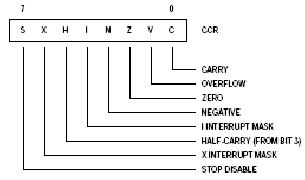
C- Carry/Borrow flag if set indicates that an arithmetic carry/borrow has occurred

V overflow if set indicates that the answer was greater that 8 bits  

Z zero flag if set if the ALU answer has produced a zero  

N - Negative if set this indicates that a negative number has been generated i.e. bit 7 = 1  

I - Interrupt mask if set stops further masked interrupts from happening

H Half carry, if set indicates that a half carry has occurred i.e. ALU result has caused a carry to occur between bit 3,4

X - Interrupt mask, if set indicates that a non masked interrupt has occurred i.e. Reset or XIRQ. Cleared by TAP or RTI

S Stop disable if set disables the use of the stop instruction, if cleared enables the stop command

The 68HC11 instruction set consists of three major groups:
 
          Maths Functions 
          Movement functions
          Processor commands
 
Before we tackle each section we shall first discuss the various addressing modes of each instruction


Related Discussions:- Software architecture of microprocessor

What is paging unit, Paging Unit Paging mechanism functions with 4K -...

Paging Unit Paging mechanism functions with 4K - byte memory pages or with a new extension available to Pentium with 4M byte-memory pages. In the Pentium, with the new 4M-byt

Illustrate what is a centrifugal force, Q. Illustrate what is a Centrifugal...

Q. Illustrate what is a Centrifugal Force? Answer:- Centrifugal force is the force that is equivalent in magnitude but opposite in direction to the centripetal force which

Interaction design and human–computer interaction, You should now have a re...

You should now have a reasonably clear understanding of what is meant by interaction design. However, there are several other terms which are often used to refer to particular aspe

Explain the input stage of an ADC, Explain the Input Stage of an ADC. ...

Explain the Input Stage of an ADC. Ans. Input Stage- In ADC at the input stage, analog voltage can contain any value in a range although the digital output can contain

Give the meaning of spc, SPC stands (A)   Standard Protocol Control ...

SPC stands (A)   Standard Protocol Control (B)   Stored Program Control (C)  Signaling and switching Centre (D)  Signaling Process Center Ans: SPC repres

What are inertial and non-inertial frame of references, Q. What are inertia...

Q. What are inertial and non-inertial frame of references? (i) Inertial (or) unaccelerated frames: Bodies in this frame follow Newton's law of intertia as well as othe

Target _self, TARGET = "_self" "_self" puts the new document in the s...

TARGET = "_self" "_self" puts the new document in the same window and frame as current document. "_self" works the same as if you hadn't used TARGET at all.

Write a recursive algorithm, Write a recursive algorithm to count the numbe...

Write a recursive algorithm to count the number of right children in a binary search tree. Write the method levelCount whose header is given below. Method levelCount returns

Determine a positive logic system logic state level, In a positive logic sy...

In a positive logic system, logic state 1 corresponds to ? Ans. For positive digital logic, we choose two voltages levels. Higher voltage shows logic 1 and a lower voltage sho

Write Your Message!

Captcha
Free Assignment Quote

Assured A++ Grade

Get guaranteed satisfaction & time on delivery in every assignment order you paid with us! We ensure premium quality solution document along with free turntin report!

All rights reserved! Copyrights ©2019-2020 ExpertsMind IT Educational Pvt Ltd