Single acting turbo prop operation:
Before moving on to double acting propellers the following diagram and explanations will help the student consolidate the information listed in the notes thus far and hopefully help towards the understanding of the operational sequence and control of a small turboprop aircraft.
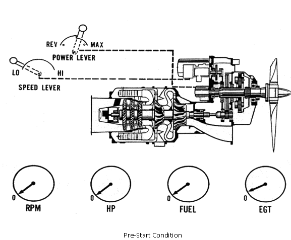
Several things should be checked prior to starting the engine. Ensure the propeller is 'on the locks'. Pull the propeller through, listening for unusual noises. Check for control lever freedom of travel and position the speed lever to the low or taxi position. Place the power lever ahead of ground idle. The preferable position is in flight idle.
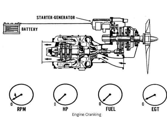
Actuate the start switch. Note the increase of RPM on the cockpit indicator as well as propeller rotation.
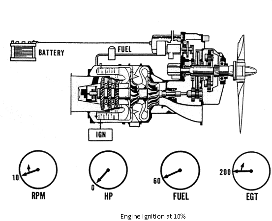
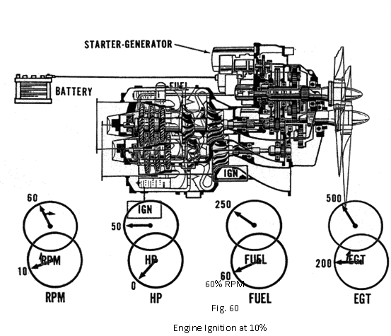
The engine will accelerate to 10 percent RPM. The EGT rise is the true indication of lightoff. If lightoff does not occur within 10 seconds after 10 percent, the start be aborted.
RPM will continue to increase, fuel and temperature will increase with temperature stabilising at the starting value. Horsepower, or torque will also begin to indicate.
As engine speed reaches 60 percent, the speed switch will send a signal to de-energise the ignition system. Horsepower has stabilised due to the fixed prop load, fuel will remain the same while temperature has decreases due to the increased air flow. The engine is now considered self-sustaining.
The engine will continue to accelerate on its own until it reaches its onspeed condition. RPM will stabilise at 65 percent. Fuel flow and temperature will have reduced and stabilised. RPM is now a function of the underspeed governor.
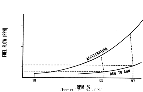
The chart at Fig, illustrates the action of the underspeed governor and the reason for the reduction in fuel and temperature. Notice that the fuel required for acceleration is greater than that required at a stabilised onspeed condition, or 'required to run'. Acceleration fuel starts at 10 percent RPM when the fuel valve opens. From that point the acceleration schedule is a function of increasing P3 air. Increasing P3 air is indicative of engine rotational speed increasing. As the engine approaches its low speed setting, the underspeed governor begins to meter fuel to the engine. It will continue to cut back on fuel flow until the stabilised RPM is achieved or when power equals propeller load.
When the engine has stabilised and all parameters are check, the propeller can be removed from the locks (Fig 63). This is necessary to allow the propeller to produce thrust which would otherwise be extremely difficult with the propeller fixed at a low blade angle. To accomplish this the power lever is moved toward reverse. By being in beta mode, blade angle is controlled by the propeller pitch control through the power lever. This will cause the propeller to move toward a reverse blade angle. This reverse blade angle is a greater load than the starting blade angle, so the operator will notice an increase in torque, fuel flow and temperature.