Simply supported beam - bending moment, Mechanical Engineering

Assignment Help:

Simply supported beam -  Bending Moment:

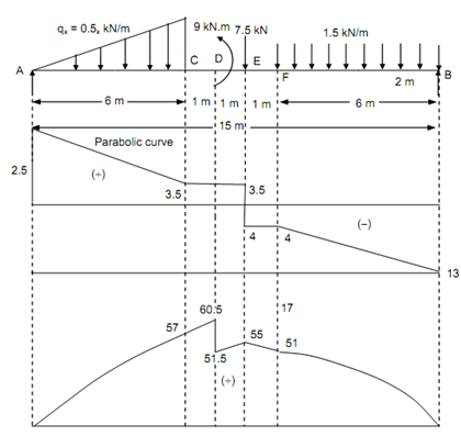
Sketch the SFD and BMD for a simply supported beam of 15 m span loaded as illustrated in Figure

1782_Simply supported beam -  Bending Moment.png

Figure

Solution

Taking moment about A,

R B   × 15 - 1.5 × 6 × (9 + (6/2)) - (7.5 × 8) + 9 - ((½) × 6 × 3 × (2/3) × 6 ) = 0

RB  = 13 kN

R A   = (( ½) × 6 × 3?)+ 7.5 + (1.5 × 6) - RB = 25.5 - 13 = + 12.5 kN

Shear Force (Beginning from the Left End A)

SF at A,        FA  = + 12.5 kN

SF at C, F C   =+ 12.5 - ((½) × 6 × 3 ) = + 3.5 kN

SF just left of E,         FE  =+ 3.5 kN

SF just right of E,      FE  =+ 3.5 - 7.5 = - 4 kN

SF at F,           FF  =- 4 kN

SF just left of B,     FB  =- 4 - (1.5 × 6) = - 13 kN = Reaction at B.

 Bending Moment (Beginning from Right End B)

BM at B,         MB = 0

BM at F,

M F      =+ (13 × 6) - (1.5 × 6 × (6/2)   =+ 51 kN-m

BM at E,      M E         =+ (13 × 7) - 1.5 × 6 × (1 + (6 /2))  =+ 55 kN-m

BM just right of D, M D =+ (13 × 8) -1.5 × 6 × (2 + (6/2)) - 7.5 =+ 51.5 kN-m

BM just left of D, M D  = + 51.5 + 9 = + 60.5 kN-m

BM at C, M C  =+ (12.5 × 6) - (½) × 3 × 6 × ((1/3) × 6 )  =+ 57 kN-m


Related Discussions:- Simply supported beam - bending moment

Determine the resultant of the loads, Determine the resultant of the loads:...

Determine the resultant of the loads: A system of loads acting on beam is shown in the figure given below. Determine the resultant of the loads. Sol.: Let R be resultant

Order sequences and order release, Order Sequences and Order Release Fo...

Order Sequences and Order Release For this system, sequences of orders for particular parts (batch size 1) are produced in the following way: for each machine, here is, for eac

Explain internal broaching - types of broaching, Explain Internal Broaching...

Explain Internal Broaching - Types of Broaching Internal broaching operation is adopted for producing internal surface such as holes, keyways and teeth of an internal gear for

Centre of gravity and centroid, Q.   Explain the terms centre of gravity an...

Q.   Explain the terms centre of gravity and centroid. Sol. : A point can be found out in a body through which resultant of all such parallel forces acts. This point through

Mr, I need rewording

I need rewording

Calculate the net positive suction head, Calculate the Net Positive Suction...

Calculate the Net Positive Suction Head A pump station has been designed to lift water out of a 6 metre deep pit (vented to atmosphere) via a centrifugal pump mounted at groun

Working principle of the petrol engine, W orking Principle of the Petrol E...

W orking Principle of the Petrol Engine: OTTO CYCLE     5-1 Suction Stroke 1-2 Adiabatic Compression Stroke 2-3 Heat Addition at the constant Volume.

Supports for rigid bodies, Supports for Rigid Bodies: In this unit, yo...

Supports for Rigid Bodies: In this unit, you have learnt to classify various types of supports and constraints, rollers, rockers, ball and socket joints, cables, short links,

Internal and external diameters - solid shaft, Internal and external diamet...

Internal and external diameters - solid shaft: Two shafts are of the similar material, length & weight. One is solid & of 100 mm diameter, the outer is hollow. If hollow shaft

Write Your Message!

Captcha
Free Assignment Quote

Assured A++ Grade

Get guaranteed satisfaction & time on delivery in every assignment order you paid with us! We ensure premium quality solution document along with free turntin report!

All rights reserved! Copyrights ©2019-2020 ExpertsMind IT Educational Pvt Ltd