Show equivalent circuit of a synchronous machine, Electrical Engineering

Assignment Help:

Equivalent Circuit of a Synchronous Machine

A review of the material about elementary synchronous machines is very helpful at this stage to recall the principles of operation for synchronous machines. To investigate the equivalent circuit of a synchronous machine, for the sake of simplicity, let us begin by considering an unsaturated cylindrical-rotor synchronousmachine. Effects of saliency and magnetic saturation can be considered later. Since for the present we are only concerned with the steady-state behavior of themachine, circuit parameters of the field and damperwindings need not be considered. The effect of the field winding, however, is taken care of by the flux produced by the dc field excitation and the ac voltage generated by the field flux in the armature circuit.

Thus, let ¯Ef be the ac voltage, known as excitation voltage, generated by the field flux. As for the armature winding, under balanced conditions of operation we will analyze it on a per-phase basis. The armature winding obviously has a resistance Ra and a leakage reactance Xl of the armature per phase.

The armature current ¯Ia produces the armature reaction flux, the effect of which can be represented by an inductive reactance Xφ, known as magnetizing reactance or armature reaction reactance. Thus Figure shows the equivalent circuits in phasor notation, with all per-phase quantities, for a cylindrical-rotor synchronous machine working as either a generator or a motor. The sum of the armature leakage reactance and the armature reaction reactance is known as the synchronous reactance,

Xs = Xφ + Xl

1227_Show Equivalent Circuit of a Synchronous Machine.png

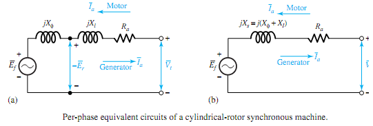
and Ra + jXs is called the synchronous impedance Zs. Thus, the equivalent circuit for an unsaturated cylindrical-rotor synchronous machine under balanced polyphase conditions reduces to that shown in Figure (b), in which the machine is represented on a per-phase basis by its excitation voltage ¯Ef in series with the synchronous impedance. Note that ¯Vt is the terminal per-phase rms voltage, usually taken as reference.


Related Discussions:- Show equivalent circuit of a synchronous machine

Binary subtraction , Binary Subtraction Negative numbers are represent...

Binary Subtraction Negative numbers are represented in 2 complement form and subtraction is also  per formed  using  2 complement  method in microprocessor. Hence we will  dis

Briefly explain about transients in circuits, Q. Briefly explain about Tran...

Q. Briefly explain about Transients in circuits? The total response of a system to an excitation that is suddenly applied or changed consists of the sum of the steady-state and

Metal–oxide–semiconductor structure, Metal-Oxide-Semiconductor Structure ...

Metal-Oxide-Semiconductor Structure A traditional metal-oxide-semiconductor abbreviated as MOS structure is acquired by growing a layer of silicon dioxide (SiO 2 ) on top of

Determine about the satellite navigation, Determine about the satellite nav...

Determine about the satellite navigation In motor vehicles system is known as satellite navigation (sat nav). On board computer contains pre-stored road maps. Vehicle's exact

Explain nodes analysis, Nodes analysis Analysis using KCL to solve for ...

Nodes analysis Analysis using KCL to solve for voltages at every common node of the network and as determines the currents by and voltages across every elements of the network.

Describe watch dog timer and reaction timer, a. Given a timer with a termin...

a. Given a timer with a terminal count and a clock frequency of 10 MHz measure the following: (i) Range & Resolution (ii) Terminal count values needed to measure 3ms interval

Determine impedance - resultant current and power factor, Determine Impedan...

Determine Impedance - Resultant current and Power factor: In series R-L circuit, illustrated in Figure , Determine 1.      Impedance, 2.      Resultant current, 3.

Show the overall output limitations of speed control, Q. Show the Overall o...

Q. Show the Overall output limitations of Speed Control? The overall output limitations are as shown in Figure. With base speed defined as the full-field speed of themotor at t

Inverter, single phase voltage source inverter complete circuit

single phase voltage source inverter complete circuit

Write Your Message!

Captcha
Free Assignment Quote

Assured A++ Grade

Get guaranteed satisfaction & time on delivery in every assignment order you paid with us! We ensure premium quality solution document along with free turntin report!

All rights reserved! Copyrights ©2019-2020 ExpertsMind IT Educational Pvt Ltd