Scan Conversion of Line with the slope (0 < m < 1)
Currently the pixel positions beside the line path are determined through sampling at Unit x intervals that is, starting from the first point. (x0, y0) of a provided line we step to all successive columns. That is x-position and plots the pixel that scan line y value is closest to the line path. Suppose we proceed in such fashion up to the kth step. The process is demonstrated in following figure. Suppose that we have determined the pixel at (xk, yk). We require deciding that pixel is to be plotted in column xk+ 1. Our options are either (xk +1, yk) or (xk + 1, yk + 1).
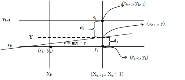
Figure: Scan conversion 0 < m < 1
On sampling position Xk + 1 the vertical pixel or say scan line separation from mathematical line i.e. y = mx + c is say d1 and d2.
Currently, the y coordinate on the mathematical line on pixel column position Xk + 1 is:
y = m (xk + 1) + c ---------------------(1)
By using figure of Scan conversion 0 < m < 1:
d1 = y - yk ---------------------(2)
= m (xk + 1) + c - yk ---------------------(3) (by using (1))
Likewise, d2 = (yk + 1) - y = yk + 1 - m (xk + 1) - c ---------------------(4)
By using (3) and (4) we get d1 - d2
d1 - d2 = [m (xk + 1) + c - yk] - [yk + 1 - m (xk + 1) - c]
= mxk + m + c - yk - yk - 1 + mxk + m + c
= 2m (xk + 1) - 2yk + 2c - 1 ---------------------(5)
As, decision parameter p for kth step that is pk is specified by
pk = Δx(d1 - d2 )---------------------(6)
Currently, a decision parameter pk for the kth step in the line algorithm can be acquired by rearranging (5) hence it involves merely integer calculations. To achieve this substitute m = Δy/Δx; here, Δy and Δx ⇒ vertical and horizontal separations of the ending point positions.
pk = Δx (d1 - d2) = Δ x [2m (xk + 1) - 2yk + 2c - 1]
= Δx [2(Δy/Δx) (xk + 1) - 2yk + 2c - 1]
= 2 Δy (xk + 1) - 2 Δxyk + 2 Δxc - Δx
= 2 Δy xk - 2 Δx yk + [2 Δy + Δx (2c - 1)]
pk = 2 Δy xk - 2Δxyk + b -------------------- (7)
Here b is constant with value b = 2Δy + Δx (2c - 1) ---------------------(8)
Note: sign of pk is as similar as sign of d1 - d2 as it is assumed like Δx > 0; here in figure of Scan conversion 0 < m < 1 , d1 < d2 i.e. (d1 - d2) is -ve that is , pk is negative so pixel Ti is more suitable option otherwise pixel Si is the proper option.
That is (1) if pk < 0 choose Ti, hence subsequent pixel option (xk, yk) is (xk + 1, yk) else (2) if pk > 0 decide Si, so subsequent pixel option after (xk , yk ) is (xk + 1, yk + 1).
At step k + 1 the decision parameter is evaluated via writing (7) as:
pk + 1 = 2Δy xk + 1 - 2Δx yk + 1 + b ---------------------(9)
Subtracting (7) from (9) we find:
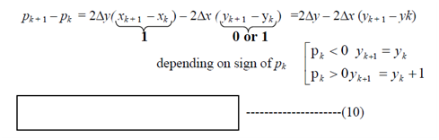
Such recursive calculation of decision parameter is preformed at all integer positions, starting along with the left coordinate ending point of line.
This first parameter p0 is calculated by utilizing Eq(7), and (8) at the beginning pixel position (x0, y0) along with m evaluated as Δy /Δx (that is intercept c = 0)
p0 = 0 - 0 + b = 2Δy + Δx (2 * 0 - 1) = 2Δy - Δx
p0 = 2Δy - Δx -----------------------(10 A)