Consider the robotic manipulator of Fig. 1, with a Revolute and a Prismatic Joint. Figure 1, shows the side view of the manipulator while figure 2. shows the top view of the manipulator. The revolute (R) joint forms the shoulder of the manipulator and the prismatic (P) the elbow. The revolute joint provides a angular motion (back and forth) about the z0 in the base coordinate frame L0. The prismatic joint provides linear motion (up and down), enabling the end-effector (comprising a gripper tool) to approach close to ground level and to manipulate objects (e.g. performing a pick and place operation). When the gripper is at rest and before any action is performed, it is assumed that the end effector is at the same height with Link1. When an object is to be picked or placed on ground level the joint moves downwards. It is assumed that the tool tip can reach ground level. This implies that the length of Link2 is at least 450mm.
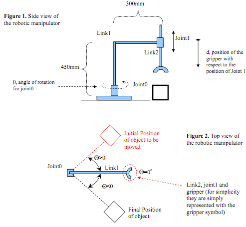
The movement of the manipulator is performed in the following way. Assume that a square block has to be moved from position 1 to position 2 as shown in fig. 2.
1. Joint0 first moves up to the desired position θ
2. Joint1 then moves down to the height d of the pellet
3. The end effector then picks the block and Joint1 returns back to its initial position d=0
4. Joint0 then moves to the next position θ
Placing many objects with the manipulator in various positions, requires to perform the above basic movement for each object sequentially i.e. move the first object, then the second, then the third etc.
We assume that:
1. The end effector picking task has a very small reaction time, so when the end effector is placed on the object it immediately grabs the object ± you don't have to consider, as soon as the object is reached, any delay due to gripper operation
2. The weights and inertia of the links are very small so all the force or torque generated by the drives of the joints is used for movement.
3. The angle when link1 is at rest is =0, when link1 moves upwards is positive >0 and when link1 moves downwards is negative θ< 0 .
Tasks:
A. Formulation:
1. Define the type of the manipulator's work envelope and its type
2. Define the manipulator configuration and choose appropriate joint drives (electric, pneumatic or hydraulic) and the relationship between the value of joint variables and actuation
Hint: In many cases prismatic joints employ linear drives that convert angular motion to linear displacement by means of a lead screw
3. Describe the models for each of the joint drives (transfer function or state-space model) ± input and outputs
4. Simulate each drive system in Matlab by applying a unit step response at each model
B. Control:
1. Design a control system for each of the drives of the joints. The combined movement of the two joints should place the gripper in the desired position.
2. Simulate the system response when applying the controller, by using the three reference signals.