Responses to exponential excitations, Electrical Engineering

Assignment Help:

Responses to Exponential Excitations

Let us consider Aest as a typical exponential excitation in which A is a constant and s is a complex- frequency variablewith a dimension of 1/second such that the exponent st becomes dimensionless.

The variable s can assume real, imaginary, or complex values. The time-invariant dc source is represented by setting s = 0. The use of s = jω would imply sinusoidal excitation.

Note that Aest is the only function for which a linear combination of

1030_Responses to Exponential Excitations.png

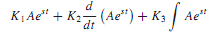
in which K1, K2, and K3 are constants has the same shape or waveform as the original signal. Therefore, if the excitation to a linear system is Aest, then the response will have the same waveform.

Recall the volt-ampere relationships (for ideal elements) with time-varying excitation.

1123_Responses to Exponential Excitations1.png

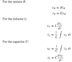
With exponential excitation in which v(t) = Vest and i(t) = Iest, it can be seen that the following holds good because exponential excitations produce exponential responses with the same exponents. (Notationwise, note that v(t) and i(t) represent the real-valued signals, whereas v(t) and i(t) represent complex-valued signals.)

1787_Responses to Exponential Excitations2.png

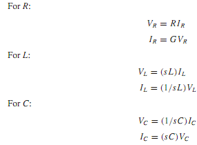
The preceding equations resemble the Ohm's law relation. The quantities R, sL, and 1/sC have the dimension of ohms, whereas G,1/sL, and sC have the dimension of siemens, or 1/ohm. The ratio of voltage to current in the frequency domain at a pair of terminals is known as the impedance, designated by Z(s), whereas that of current to voltage is called the admittance, designated by Y(s). Note that both the impedance and the admittance are in general functions of the variable s, and they are reciprocal of each other. Such expressions as Equations 15 through 16 relate the amplitudes of the exponential voltages and currents, and are the frequency-domain representations of the elements. Networks drawn using impedance or admittance symbols are known as transformed networks, which play a significant role in finding the network response, as shown in the following examples.


Related Discussions:- Responses to exponential excitations

Explain memory mapped i/o scheme, Explain Memory Mapped I/O Scheme. Me...

Explain Memory Mapped I/O Scheme. Memory Mapped I/O Scheme: In such scheme there is only one address space. These address space is defined as all possible addresses which m

Determine required output power, Q. Two stations (using identical antennas,...

Q. Two stations (using identical antennas, with diameters of 50λ and aperture ef?ciencies of 0.6 at 35 GHz) are separated by 30 km. With negligible antenna losses, antenna connecti

Fixed bias, Fixed bias (base bias): Diagram: Fixed bias (Base ...

Fixed bias (base bias): Diagram: Fixed bias (Base bias) This type of biasing is also known as  base bias . In the instance above figure, the single power source (

Low pressure gas hazards, Low Pressure Gas Hazards : Safety screens and wi...

Low Pressure Gas Hazards : Safety screens and wire-mesh guards should be placed round evacuated glassware and safety goggles or a face shield must be worn against the possibility

Define the universal property of nand and nor gates, Define The universal p...

Define The universal property of NAND and NOR Gates? The NAND and NOR gates are called universal gates, because any gate can build by using these two gates. The univers

Mr, what is pole core and pole shoe in a dc machine

what is pole core and pole shoe in a dc machine

Carrier modulation by digital signals, Q. Carrier Modulation by Digital Sig...

Q. Carrier Modulation by Digital Signals? Digitally modulated signals with low-pass spectral characteristics can be transmitted directly through baseband channels (having low-p

Managing a Professional Engineering Project, Design a solar powered electri...

Design a solar powered electric vehicle charging station in a liquid gas station

Determine currents in the circuits, Determine currents in the circuits: ...

Determine currents in the circuits: Determine currents I 1 and I 2 in the given circuits by applying KVL. Solution We apply KVL for first loop : 10 = 1 I 1   + 1

List the different types of flags, List the different types of flags affect...

List the different types of flags affected by the arithmetic and logic operations. Carry flag, Auxiliary carry flag , Parity flag, Sign flag, Zero flag

Write Your Message!

Captcha
Free Assignment Quote

Assured A++ Grade

Get guaranteed satisfaction & time on delivery in every assignment order you paid with us! We ensure premium quality solution document along with free turntin report!

All rights reserved! Copyrights ©2019-2020 ExpertsMind IT Educational Pvt Ltd