Removing Aircraft Engines:
To prepare an aircraft for engine removal, check that the aircraft weight and balance will not be adversely effected when the engine is removed. Most engines weigh between 0.5 and 1 ton. Trestles may be required to stabilise the fore and aft axis of the aircraft.
The aircraft fuel system does not have to be drained, but the LP fuel valve must closed and a label attached to the LP Cock handle, in the flightdeck, to prevent inadvertent operation. In addition, the aircraft should be made electrically safe which will entail isolation of the engine starting and ignition system.
Planning is an essential part of any engine removal activity. The Supervisor and personnel involved, should ensure that all necessary resources, such as sufficient manpower, special tools, lifting equipment and an engine transit / storage stand, are available.
The engine access doors and fairings will either have to be removed or supported clear of the engine.
Due to restricted access of some engine accessories and components, it is, in some cases, much easier to remove these items with the engine installed in the aircraft.
Once the engine has been initially prepared for removal (accessories removed etc) the procedure of disconnecting the engine systems, at the engine/ aircraft interface, can begin. Most engines employ quick release plugs and sockets for ease of disconnection of the electrical systems, however some electrical systems, with heavier duty cables, such as the starter and generator cables, may be bolted connections. Disconnect any cable cleats going across the engine / airframe interface.
The hydraulic pipes are usually quick release/self-sealing connections at both the hydraulic pump and the engine / airframe interface. Air supply connections will generally interface with a ‘vee band' type of clamp or a bolted connection.
The engine LP fuel inlet pipe must be drained, before disconnection, into a suitable container and the waste fuel disposed off in an approved manner. With the exception of the main engine bearers, all mechanical links must be released and either removed or tied back to prevent fouling during the removal operation.
If the engine is not being replaced or refitted immediately, all open pipes must be blanked off to prevent foreign particle ingress and all electrical plugs tied back and protected.
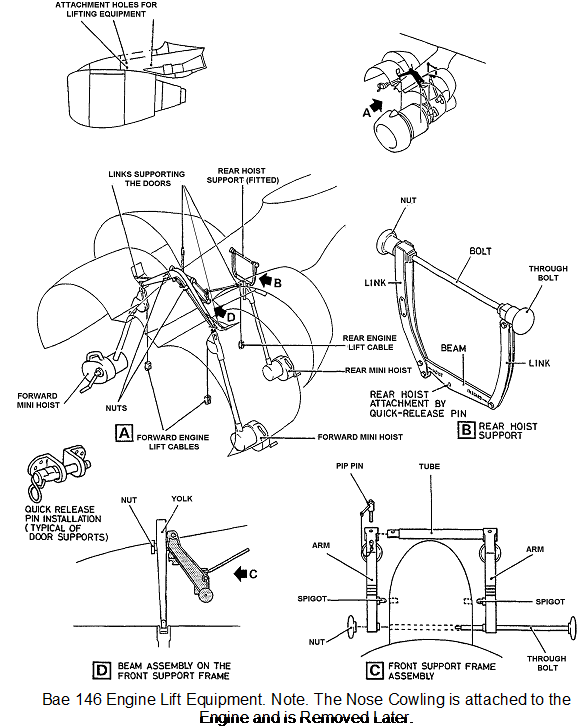
Once satisfied that the engine is ready for removal the lifting equipment can be fitted in accordance with the AMM. Jet engines are installed and removed utilising gantry cranes, mobile cranes or in many cases by use of 2,3 or 4 mini hoists.
Whatever method is used the lifting equipment must be inspected before use. Particular attention should be paid to ensuring that the equipment has approval documentation and is of the correct ‘safe working load' for the task. Cables should not show evidence of twisting or fraying and end fittings should be free of damage, corrosion etc. When mini hoists are used, the brake and clutch mechanisms of each hoist should be functionally checked and that the correct hoist is being used as similar units are rated at different settings.
Supervisors should double check that all the lifting equipment is serviceable and correctly fitted prior to commencing the removal process. The supervisor should also carry out a final check of the engine / airframe disconnect points to satisfy himself/herself that the engine and equipment is safe for removal.
Each winch / hoist is to be manned at all times during the removal process and at least one person who can check the engine to ensure it remains in a safe condition during removal. The supervisor must ensure that all team members are fully aware of the process and briefed on what is required of each individual. All instructions should be given in a clear and unambiguous manner and where hand signals are required, all members can see the supervisor and are aware of their meaning. Only the supervisor of the task should issue instructions during the process and unnecessary talk and noise (i.e. riveting operations in vicinity) minimised or stopped.
Immediately prior to removing the engine and finally releasing the engine mounts / attachments, the weight of the engine must be ‘taken' by the lifting equipment. This will ensure that there is no unnecessary ‘jerking' or ‘snatching' of the cables. With mini hoists this is achieved by winching the cable in until the clutch in the handle breaks (Always re-engage the handle before progressing further). At this point the effectiveness of the brake unit in the mini hoist should be checked following the relevant manufacturers procedures. Once the supervisor is satisfied that all procedures have been followed correctly and that all resources are in place the engine mountings / bearers can be disconnected and the engine removed / lowered from its housing. At all stages of the removal procedure checks should be carried out to ensure that the engine does not become caught on the airframe structure or components.