Radiation intensity pattern of antennas, Electrical Engineering

Assignment Help:

Q. Radiation intensity pattern of Antennas?

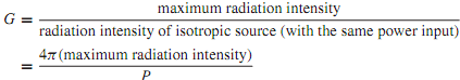
Antennas do not radiate power equally in all directions in space. The radiation intensity pattern describes the power intensity (which is power per unit solid angle, expressed in units of watts per steradian) in any spatial direction. Conceptually it is convenient to define an isotropic antenna as a lossless antenna that radiates its power uniformly in all directions. Although an isotropic antenna cannot be realized in practice, it serves as a reference for comparison with real antennas. The radiation intensity for such an antenna, with input power P, is a constant in any direction, given by P/4π. The power gain G of a realistic antenna is a measure of the maximum radiation intensity of the antenna as comparedwith the intensity thatwould result froman isotropic antenna, with the same power input. G is then expressed as

576_Radiation intensity pattern of Antennas.png

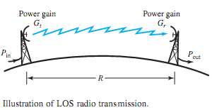
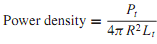
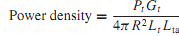
Referring to Figure when a power Pt /Lt is applied to the transmitting antenna, let us find the signal power Sr available to the receiver from the receiving antenna. An isotropic transmitting antenna would cause a radiation power density (power per unit area of a sphere) of

518_Radiation intensity pattern of Antennas1.png

For a practical antenna that has power gainGt and loss Lta relative to an isotropic antenna, Equation (15.1.19) would be modified as

1347_Radiation intensity pattern of Antennas2.png

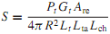
We shall assume that the transmitting and receiving antennas (reciprocal elements) point directly toward each other, so that their gains are maximum. Letting Lch denote any losses incurred by the wave in the channel (medium), and Are be the effective area of the receiving antenna, the power that the receiving antenna is able to produce is given by

1031_Radiation intensity pattern of Antennas3.png

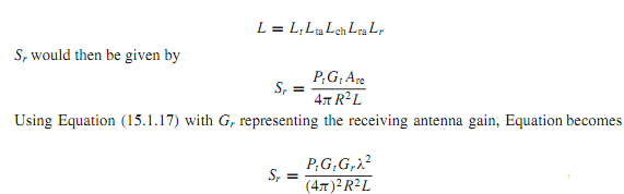
Accounting for the receiving antenna loss and receiving-path losses, a total system loss L can be defined as

1845_Radiation intensity pattern of Antennas4.png

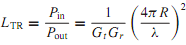
Quite often, for simplicity, in the case of LOS radio transmission illustrated in Figure, the transmission loss for a path of length R is given by

2476_Radiation intensity pattern of Antennas5.png

1630_Radiation intensity pattern of Antennas6.png


Related Discussions:- Radiation intensity pattern of antennas

Develop a general expression for the force, Consider an electromagnet, as s...

Consider an electromagnet, as shown in Figure, which is used to support a solid piece of steel and is excited by a coil of N = 1000 turns carrying a current i = 1.5 A. The cross-se

Find the impedance of the series combination, Q. An RL series circuit carri...

Q. An RL series circuit carries a current of 0.02 cos 5000t A. For R = 100  and L = 20 mH, find the impedance of the series combination and determine the voltage across the series

Difference between object oriented and object based language, Object based ...

Object based languages don't support Inheritance where as object oriented supports. C# is a object oriented language due to it supports inheritance and asp.net is not a language it

Induction motor, A very widely used alternative form of synchronous motor i...

A very widely used alternative form of synchronous motor is the  ' indu c tion motor'. This has the advantage that it does not require an auxiliary motor to run the rotor up t

OSCILLATORS, DESIGN A WIEN OSCILLATOR THAT OSCILLATE AT 25KHZ

DESIGN A WIEN OSCILLATOR THAT OSCILLATE AT 25KHZ

Working hydro-electric power plant, With the help of neat diagrams illustra...

With the help of neat diagrams illustrate the construction and working of various elements used in hydro-electric power plant. Compare hydro-electric power plant with other type

Basis of the electric solenoid actuator, There is a force on the plunger re...

There is a force on the plunger required to do to move it into or out of the gap and work must be done by or against this force. The conservation of energy dictates that the change

Oscilloscope probe compensation, Q.   what is oscilloscope probe compensati...

Q.   what is oscilloscope probe compensation and how is it adjusted?  What effects are noted when the compensation is not correctly adjustment? Direct Probe: This probe  is

Determine the transfer function, Q. For the networks shown in Figure, deter...

Q. For the networks shown in Figure, determine the transfer function G(s) = V o (s)/V i (s).

.energy, units of potential energy

units of potential energy

Write Your Message!

Captcha
Free Assignment Quote

Assured A++ Grade

Get guaranteed satisfaction & time on delivery in every assignment order you paid with us! We ensure premium quality solution document along with free turntin report!

All rights reserved! Copyrights ©2019-2020 ExpertsMind IT Educational Pvt Ltd