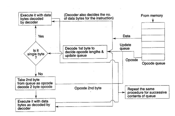
Queue Operation :

RQ/CT0, RQ/G1-Request/Grant: These pins are utilized by other local bus masters, in themaximum mode, to force the processor to release the local bus at the end of the processor's current bus cycle. Each of the pins is bi- directional with RQ/GT () having greater priority than RQ/GT1. RQ/GT pins have pull up internally resistors and can be left unconnected. The request& grant sequence is described below.
1) A pulse1 clock wide from another bus master requests the bus access to 8086.
2) During 74 (current) or T, (next) clock cycle, a pulse 1 clock wide from 8086 to the requesting master, show that the 8086 has allowed the local bus to float and that it will enter the "hold acknowledge" state at next clock cycle. The CPU's bus interface unit is probable to be disconnected from the local bus of the system.
3) A 1 clock wide pulse from the master indicates to 8086 that the 'hold' request is just going to end and the 8086 can regain control of the local bus at the next clock cycle.
Thus each master to master exchange of the local bus is a sequence of 3 pulses. There might be at least 1 dead clock cycle after each bus exchange. The request &grant pulses are active low. Those are received for the bus requests when 8086 is performing I/O cycle or memory, the granting of the bus is ruled by the rules as discussed in case of, HLDA andHOLD in minimum mode.
Yet now, we have described the architecture and pin configuration of 8086. Next, we will study some operational features of 8086 based systems.