Prove the parallelogram law of forces - mechanics, Mechanical Engineering

Assignment Help:

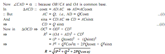
Prove the parallelogram law of forces:

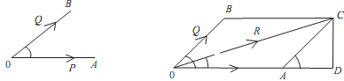
Assume that the two forces P and Q act at a point 'O' as shown in figure given below. The force P can be represented in magnitude and direction by vector OA, While force Q is represented in magnitude and direction by vector OB, Angle between the two force is 'a'. The resultant can be denoted by vector OC as shown in the figure given below. Drop perpendicular from C on OA.

Let,

P,Q = Forces whose resultant is needed to be found out.

θ= Angle that the resultant forces makes with one of the forces

α= Angle between the forces P and Q

1071_Prove the parallelogram law of forces.png

It is the magnitude of resultant 'R'
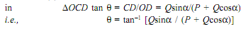
 

2383_Prove the parallelogram law of forces1.png

Direction ( θ ):

865_Prove the parallelogram law of forces2.png


Conditions

(i) Resultant R is max when two forces collinear and are in the same direction.

 2380_Prove the parallelogram law of forces3.png

(ii) Resultant R is min when two forces collinear but acting in the opposite direction.

That is  α = 1800    =>   Rmin = P- Q

(iii) If a = 900, that is when the forces act at right angle, then

R =   P2  + Q2

(iv) If the two forces are equal that is, when P = Q  =>R = 2P.cos(θ/2)


Related Discussions:- Prove the parallelogram law of forces - mechanics

What are the capabilities of step, What are the capabilities of STEP In...

What are the capabilities of STEP Industry-Developed STEP Capabilities AP-203, Configuration Control for 3D Design of Mechanical Parts and Assemblies, provides a very robust

Truss arrangement assuming the members are beams, Q2.1  Using the stiffness...

Q2.1  Using the stiffness method calculate axial forces and the deflections of the joints of the truss shown in the FIG. The truss was built using 50 mm x 50 mm x 5 mm SHS with  E

Explain degree of freedom - jig and fixture, Explain Degree of Freedom - Ji...

Explain Degree of Freedom - Jig and Fixture The complete location of components inside a jig or fixtures can be understood with the help of figure. The work piece is a

Equiliubrium, Review questions condition of equilibrium grade 11 unit 7

Review questions condition of equilibrium grade 11 unit 7

What is auto-ignition temperature, Q. What is Auto-Ignition Temperature? ...

Q. What is Auto-Ignition Temperature? Auto-Ignition Temperature (AIT) - The auto-ignition temperature is the temperature at which a product will burn without application of any

Explain about wire-frame model, Q. Explain about wire-frame model? A wi...

Q. Explain about wire-frame model? A wire-frame model of an object is the simplest, but more verbose, geometric model that can be used to represent it mathematically in the com

Casting, What is the difference between blowholes & porosity in casting ?

What is the difference between blowholes & porosity in casting ?

Describe inverse reflection, Objective type/ short-answer type questions. ...

Objective type/ short-answer type questions. Describe the following :- a. Illustrate what do you mean by CAD/ CAM b. Discuss the storage device used in computer. c. Wha

Cylinder head de-carburising and valve lapping, Cylinder Head De-carburisin...

Cylinder Head De-carburising and Valve Lapping: Cylinder head mounts on the top of the engine cylinder, the inner side of the cylinder head is always in direct contact of combusti

Write Your Message!

Captcha
Free Assignment Quote

Assured A++ Grade

Get guaranteed satisfaction & time on delivery in every assignment order you paid with us! We ensure premium quality solution document along with free turntin report!

All rights reserved! Copyrights ©2019-2020 ExpertsMind IT Educational Pvt Ltd