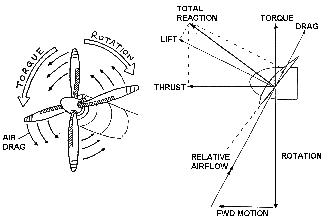
Propeller terminology, Other Engineering

Assignment Help:

PROPELLER TORQUE

Propeller torque is produced by the aerodynamic drag on the blades when in motion. Propeller torque acts in the plane of rotation and opposes engine torque. When propeller torque and engine torque are equal the propeller will rotate at constant speed.

644_PROPELLER TERMINOLOGY.png 
BLADE FORCES

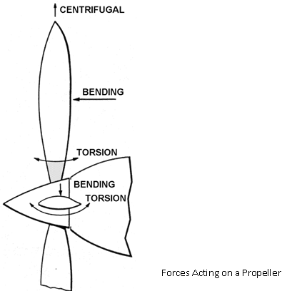
A propeller has to be capable of withstanding severe stresses that are greater near the hub and are caused by centrifugal forces and thrust. The force tending to through the blade from the hub is often as much as 22 tons. The stresses increase in proportion to the R.P.M. The blade face is also subjected to tension from the centrifugal force and additional tension from the bending. For these reasons, nicks or scratches on the blade can cause failure linked with stress corrosion.

BLADE RIGIDITY

A propeller must also be rigid enough to prevent flutter, a type of vibration in which the ends of the blade twist back and forth at high frequency around an axis perpendicular to the engine crankshaft. Flutter is often accompanied by a distinctive noise frequently mistaken for exhaust noise. The constant vibration tends to weaken the blade and may eventually cause failure.

FORCES ACTING ON PROPELLER BLADES

• Bending - Due to thrust and torque forces on the blade.
• Centrifugal - Caused by the propeller blade mass rotating at high speeds.
• Torsion - Due to the affects of CTM and ATM (see pages1-7 &1-8) and pitch change loads.
• Thrust is the component acting at right angles to the plane of rotation.
• Torque is the component acting in the plane of rotation opposing engine torque and is the resistance offered by the propeller to rotation.

1655_PROPELLER TERMINOLOGY1.png

Thrust and Torque values developed by the propeller depend on the angle of attack, the R.P.M. and air density. As air density increases so will thrust, but as increased resistance is felt by the propeller, torque will also increase. Thrust and torque will alter in direct proportion to propeller speed and any increase in the Angle of Attack (below stalling speed) will produce more thrust and torque. There is an optimum angle of attack for all propellers, usually about 40.

The aerodynamic of the propeller can most easily be understood if the action of the propeller is considered. The motion is both rotational and forward, and as far as the forces are concerned, the result is the same as if the blade were stationery and the air were coming at it from a direction opposite its path. The air deflection produced by this angle causes the dynamic pressure at the engine side of the propeller blade (the blade face) to be greater, thus producing thrust.


Related Discussions:- Propeller terminology

Balanced mutual fund, Balanced Mutual Fund The mutual fund that objective i...

Balanced Mutual Fund The mutual fund that objective is a balance of stocks & bonds. Balanced funds refer to be less volatile than stock only funds. The return or principal value of

Architecture.., draw folded plate roof structure on multi purpose hall?

draw folded plate roof structure on multi purpose hall?

End centered tetragonal lattice in the bravis list, Q.  There is no end ce...

Q.  There is no end centered tetragonal lattice in the bravis list, but there is an end centered orthorhombic lattice. Explain why this is so? Ans.  A tetragonal system is

Show down any banking products and services offered, Question: a) E-b...

Question: a) E-banking is defined as the automated delivery of new and traditional banking products and services directly to customers through electronic, interactive commun

Assembly buildings - common fault, Assembly buildings - fire risk assessmen...

Assembly buildings - fire risk assessment: Common faults found in assembly buildings are: Combustible items left in protected routes or bedroom corridors Locked exi

Chvorinov''s rule, Q. Why is it desirable to design a casting to have direc...

Q. Why is it desirable to design a casting to have directional solidification sweeping from the extremities of the mould to riser based on Chvorinov's rule? What would be an ideal

Digital signal processing, compute IDFT using DIT and DFT X(K)={20,-5.828-j...

compute IDFT using DIT and DFT X(K)={20,-5.828-j2.414,0,-0.172-j0.412,0,-0.172+j0.414,0,-5.828+j2.414}

Edgewise compression test on a sandwich structure , This test gives a basis...

This test gives a basis for evaluating the load-bearing capability of a sandwich structure when loaded in compression. The specimen should be at least 50 mm wide and the length sho

Construct the element matrix numerically using the 2, 1. The cantilever bea...

1. The cantilever beam-like structure shown below is modeled using a 2 x 10 mesh of rectangular four-node plane stress elements of equal size. Geometric boundary conditions at x ?

Write Your Message!

Captcha
Free Assignment Quote

Assured A++ Grade

Get guaranteed satisfaction & time on delivery in every assignment order you paid with us! We ensure premium quality solution document along with free turntin report!

All rights reserved! Copyrights ©2019-2020 ExpertsMind IT Educational Pvt Ltd