Propeller pitch control:
Before looking at propeller pitch control an understanding of the relationship between the 'Power Lever' and the 'RPM (condition / speed) Lever' with regard to power management control, the following text is related to a 'fixed shaft', coupled turbo, propeller.
The function of the power management system is to provide a means for controlling load and power. To do this a basic system utilising a lever to control power, and separate lever to control propeller load might be used. Moving the fuel lever alone would cause RPM to increase or decrease, but until the pitch lever is moved no real thrust would be produced. The same could be said about using the pitch lever alone. RPM fluctuations can be caused by varying propeller load, but no real operator of such a system was extremely good, both levers could be worked simultaneously. This would keep RPM constant and give useful thrust with power.
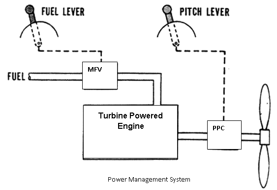
Rather than depend on the skillful movement of two separate levers the two functions are incorporated into one lever, the Power Lever. Through a system of cams and linkages it will be rigged to give two modes of operation, 'BETA' mode and 'Prop Governing' mode.
When the power lever is moved between Flight Idle (FI) and Reverse (Rev) it will be operating in the BETA mode with the Propeller Pitch Control (PPC) directly controlling blade angle. From FI to Max. the propeller governor will adjust blade angle in response to the fuel flows demanded by the Manual Fuel Valve (MFV) situated with the Fuel Control Unit.
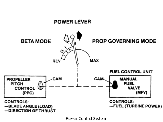
When the power lever is advanced forward from the flight idle detent, the propeller pitch control cam will normally hold the propeller at a fixed pitch. The manual fuel valve cam will then cause fuel to increase and RPM to increase eventually giving authority to the propeller governor, see following diagram.
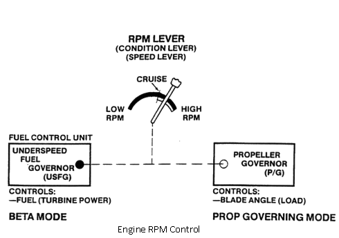
Earlier with the constant speed theory it was pointed out that the engine, with load and power equal, would operate at basically one RPM. Because of different operating conditions, such as taxiing or cruise, it becomes necessary to operate at some other RPM besides 100 percent. This is due to the need for noise reduction, fuel economy or operation at minimum load. The only function of the speed lever is to set engine operating RPM. To aid the speed lever, it is linked to the underspeed fuel governor and the propeller governor. The speed lever is used to 'calibrate' or set each governor RPM limit. With the speed lever in the low or taxi position, the underspeed governor is set to 96 percent RPM. When the speed lever is advanced to the high or takeoff position the underspeed governor is set to 97 percent RPM, the propeller governor is set to 100 percent RPM and will not be effective till this RPM is attained by forward movement of the power lever.